
Operating Instructions and Installation Instructions


ComNav Vector G2 & G2B Installation & Operation Appendices
Document PN 29010078 V2.0 - 91 -
DRAFT #3 – 29 May 2009
Differences between Cables
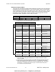
There have been five different standard cables supplied with ComNav Vector G2 & G2B GPS
Compasses, across the three generations – three 15 metre cables, and two 30 metre cables.
The main difference between the various cables is in the colour-coding of the wires. The wire
colour codes depend on the cable’s “marking” number (which is in fact the Hemisphere GPS
part number) on the cable’s label. However, all cables of a given length have the same
ComNav part number, regardless of colour coding or marking.
Part Number
31110039 31110040
Length
15 metres 30 metres
Marking 1
051-0063-003 051-0063-004 051-0157-002 051-0098-001 051-0158-001
Table 25 – Cable Types
1 The Marking is on a plastic sleeve located near the connector.
Shipped On Vector Generation
1
st
2
nd
, 3
rd
2
nd
, 3
rd
15 m
051-0063-003 051-0063-004 051-0157-002
30 m
051-0098-001 051-0158-001
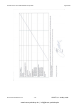
Signal
Description
(alternate signal) 3
Red 1 Red 1 Red 1 n/a Power Input
Black 1 Black 1 Black 1 n/a Power Ground
Blue Blue Blue RS-232, Tx Port A Transmit
Black
Blue,
White stripe
Black,
Blue stripe
RS-232, Rx Port A Receive
Green Green Green RS-422, ‘B’
Black
Green,
White stripe
Black,
Green stripe
RS-422, ‘A’
Port A Transmit
Brown Brown Brown RS-232, Tx
Port B Transmit
(Secondary Port A Tx)
Black
Brown,
White stripe
Black,
Brown stripe
RS-232, Rx
Port B Receive
(Secondary Port A Rx)
Black
White,
Black stripe
Grey RS-232, Gnd Signal Ground
Yellow Yellow Yellow RS-422, ‘B’
Black
Yellow,
Black stripe
Yellow,
Black stripe
RS-422, ‘A’
Port B Transmit
(Secondary Port A Tx)
Orange Orange n/a HCMOS, ‘B’
Black
Orange,
White stripe
n/a HCMOS, ‘A’
1 pulse/second
timing output
White White n/a
n/a
(RS-232, Tx)
Not connected
(Port B Tx)
n/a n/a White n/a Alarm Output Pin 1
Wire Colour
n/a n/a
White,
Red stripe
n/a Alarm Output Pin 2
Bare Wire Bare Wire Bare Wire 2 n/a
Drain for RF Shielding
!! DO NOT CONNECT !!
Table 26 – Colour Coding of All Standard Cables
1 The Power Input & Ground (Red, Black) wires are 18 AWG; all the other insulated
wires are 24 AWG.
2 The Drain wire on the 2
nd
/3
rd
generation’s 30m cable is insulated with black heat-shrink.
3 Some of the signal descriptions apply only to the 2
nd
& 3
rd
generations; the alternate
signal listed in parentheses in those cases is for the first-generation only. The RS-232
Port B on the 1
st
generation only had the Tx signal. The RS-232 Secondary Port A
was useable only for special purposes.
www.busse-yachtshop.de | info@busse-yachtshop.de