
Operating Instructions and Installation Instructions


ComNav Vector G2 & G2B Installation & Operation Installation
Document PN 29010078 V2.0 - 35 -
DRAFT #3 – 29 May 2009
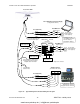
To other
NMEA equipment
Autopilot System
(Commander P2 shown)
NMEA 0183
In-2 OutIn-1
Port B (RS-422)
YELLOW
YELLOW W/ BLACK STRIPE
Heading Source : NAV IN1
Speed Source : NAV IN1
Navigation Source : NAV IN2
GREY
RS-232 Signal Ground
Port A (RS-232)
BLUE
BLACK w/ BLUE STRIPE
B
A
B
A
Tx
Rx
B
A
B
A
User-supplied
cables or wires
Tx
Rx 2
3
5
PC COM Port n*
Signal & Pin #
PC for Navigation Control & Display
(using suitable software)
D-Type 9 pin
Female Connector
(user-supplied)
Tx
Rx 2
3
5
D-Type 9 pin
Female Connector
(user-supplied)
PC COM Port n*
Signal & Pin #
* COM Ports used for
G2 & NMEA connections
are user-selected,
but MUST be different
In A
Out B
In B
Out A
RS-422 RS-232
Tx
Rx
Sig Gnd
Pwr Gnd
NMEA 0183 RS-232
Convertor
B
A
Ship’s Battery **
** may not be needed – depends on convertor
Vector G2 or G2B
From other
NMEA equipment
This connection is needed only if
the Navigation program requires
“autopilot status” information
Use one or the other wire pair
into the Convertor inputs
Figure 15 – Typical Wiring with a PC-based Navigation Program
www.busse-yachtshop.de | info@busse-yachtshop.de