
Operating Instructions and Installation Instructions


ComNav Vector G2 & G2B Installation & Operation Installation
Document PN 29010078 V2.0 - 33 -
DRAFT #3 – 29 May 2009
DE9 Connectors
To connect either of the G2’s RS-232 ports to a PC serial port (or to the DE9-P end of a
USB-to-Serial adapter), connect the wires to a DE9 female connector (a “socket type”, aka
DB9-S) as follows:
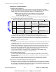
DE9 Pin Wire Color G2 Signal COM Port Signal
2 Blue Port A Transmit data Receive Data
3 Black w/ Blue Stripe Port A Receive data Transmit Data
2 L Brown Port B Transmit data Receive Data
3 L Black w/ Brown Stripe Port B Receive data Transmit Data
5 Grey Signal Ground Signal Ground
Table 4 – PC COM Port (DE9) to G2’s RS-232 Port A or B
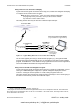
DB25 Connectors
If the PC has a DB25 COM port connector, connect the wires from the G2 to a DB25 female
connector (aka DB25-S) as follows:
DB25 Pin Wire Color Signal COM Port Signal
3 Blue Port A Transmit data Receive Data
2 Black w/ Blue Stripe Port A Receive data Transmit Data
3 L Brown Port B Transmit data Receive Data
2 L Black w/ Brown Stripe Port B Receive data Transmit Data
7 Grey Signal Ground Signal Ground
Table 5 – PC COM Port (DB25) to G2’s RS-232 Port A or B
L Caution! You can NOT wire both of the G2’s RS-232 ports to one PC COM
port simultaneously!
You will probably only be using the G2’s RS-232 Port A, when
connecting to a PC.
However, if you do wish to connect to both of the G2’s RS-232 ports
simultaneously, you will need to have two COM ports on the PC, with
each wired as listed above
Be sure to wire the Signal Ground to
BOTH COM ports!
Note: none of the other RS-232 signals that are normally available on
PC COM ports (& sometimes used by the ports &/or equipment
connected to them), such as the “status” & “flow control” signals
(RTS, CTS, DSR, DCD, etc.), are available on, nor used by, the G2’s
serial ports.
www.busse-yachtshop.de | info@busse-yachtshop.de