
Operating Instructions and Installation Instructions


ComNav Vector G2 & G2B Installation & Operation Installation
Document PN 29010078 V2.0 - 32 -
DRAFT #3 – 29 May 2009
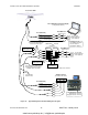
Interfacing to a PC
PC COM Ports
PC serial ports – commonly referred to as “COM ports” – always use RS-232 signal levels,
and so the only possible direct connection to the Vector G2 is via the G2’s RS-232 signals.
L If it is necessary to connect a PC to any RS-422 signals (for example,
when the PC is being used to run a Navigation program, which sends
steering commands to an NMEA 0183 autopilot – i.e., at RS-422
levels), a signal level convertor will be required (see page 36).
PC COM p
o
rts typically use a DE9
5
male (a “pin type”, aka DE9-P) connector; older PCs may
use a DB25 (aka DB25-P) connector instead.
• Desktop PCs sometimes have 2 (or more) COM ports, although newer models
usually only have one COM port. It is possible to add COM ports to most desktop
PCs, by adding a suitable “COM Port Expander” card.
• Laptop PCs usually have only one COM port.
• Many newer PCs – desktops & especially laptops – do not have a real “COM port”.
Instead, they only have one or more USB ports, and use driver software to allow
application programs to access the USB ports as “virtual COM ports”.
⇒ If the PC only has USB ports, an external USB-to-Serial adapter will be required,
since the G2 does not have a USB interface. These adapters typically have a
USB ‘A’ size plug at one end, and a DE9 male connector at the other end.
Most brands of adapters should work fine. A number of different ones have been
tried at ComNav, all with success (in fact, a “USB to 4 Serial Ports” adapter is
used by our Production & Testing staff when working on G2s).
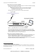
D Connector Pinouts
The figure bel
ow sho
ws the pin-numbering scheme for a PC COM port’s DE9 & DB25
connectors. This figure can be looked at in two ways:
• It is the view from the outside of the PC, looking at the pins of the male connector in
the PC, typically located somewhere on the back panel of the PC.
• It is also the view of matching female connector (aka a “socket type” – a DE9-S or a
DB25-S) when looking at the back – i.e., wire side – of that connector, on the cable
that plugs into the PC’s male connector (DE9-P or DB25-P).
Figure 13 – DE9 & DB25 Pin Numbering
5
These connectors are often referred to as “DB9”, but that is technically incorrect. The letters “B” & “E” designate the
shell sizes; a B shell is much bigger than an E shell – it can hold up to 25 pins, compared to 9 or 15 pins in an E shell.
www.busse-yachtshop.de | info@busse-yachtshop.de