
Operating Instructions and Installation Instructions


ComNav Vector G2 & G2B Installation & Operation Installation
Document PN 29010078 V2.0 - 31 -
DRAFT #3 – 29 May 2009
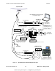
WHITE & WHITE w/ RED STRIPE
Alarm Contacts
Alarm
System
Port A (RS-422)
GREEN
BLACK w/ GREEN STRIPE
B
A
Navigation System Controller or Display
(Chartplotter, Radar, etc.)
NMEA 0183
In Out
To other
NMEA equipment
Autopilot System
(Commander P2 shown)
NMEA 0183
In-2 OutIn-1
Port B (RS-422)
YELLOW
YELLOW w/ BLACK STRIPE
To Navigation System Controller
&/or other NMEA equipment
Heading Source : NAV IN1
Speed Source : NAV IN1
Navigation Source : NAV IN2
GREY
RS-232 Signal Ground
Port B (RS-232)
BROWN
BLACK w/ BROWN STRIPE
Port A (RS-232)
BLUE
BLACK w/ BLUE STRIPE
RS-232
Tx GndRx
GPS Compass Display System
(Navigator G2 shown)
Other Equipment
using RS-232
RED (18 AWG)
Fuse
or Breaker
Power
Switch
BLACK (18 AWG)
Ship’s
Battery
11 – 36 VDC
+
-
Cut off & tape back
Shield Drain wire
B
A
B
A
Tx
Rx
Tx
Rx
B
A
B
A
User-supplied
cable or wires
Vector G2 or G2B
Figure 12 – Typical Wiring Diagram of a Vector G2 System (with Autopilot & Compass Display)
www.busse-yachtshop.de | info@busse-yachtshop.de