
Operating Instructions and Installation Instructions


ComNav Vector G2 & G2B Installation & Operation Installation
Document PN 29010078 V2.0 - 30 -
DRAFT #3 – 29 May 2009
Interfacing to a ComNav Autopilot
Commander P2 or Admiral P3
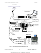
Figure
12 shows the typical connections used with a ComNav Commander P2 Autopilot
System (an Admiral P3 would be wired identically), a ComNav Navigator G2 GPS Compass
Display System, and a generic Chartplotter or other type of Navigation System.
Note: this wiring information assumes that the G2 is in its factory-default
configuration: Autopilot data on Port B, and General Navigation data
on Port A (see pages 45 & 46).
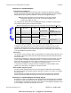
The wi
ring fro
m the G2 is to the P2’s J9
– NAV I/O connector, as follows (a small image of
the connector’s label is shown to the left of the table):
Note: all current-build P2/P3 SPUs have an error on this label – but the image below is correct.
J9 Pin Wire Color Signal Signal Data Carried
IN-2B user-supplied 1 RS-422, ’B’
IN-2A user-supplied 1 RS-422, ‘A’
from Chartplotter,
etc.
Navigation:
Waypoints, Position, etc.
IN-1B Yellow RS-422, ‘B’
IN-1A Yellow w/Black stripe RS-422, ‘A’
from G2,
Port B Transmit
Heading, Speed
OUT-1A user-supplied 1 RS-422, ‘A’
J9
IN
2A
2B
CH
1A
1B
OUT
NAV I/O
GD
B
A
OUT-1B user-supplied 1 RS-422, ’B’
to Chartplotter,
etc.
Autopilot status
Table 3 – Commander P2 Connection Details
1 These wires are supplied by the user, thus colours are not specified here.
In addition to the above wiring, the Commander P2 must be configured to look for both
heading and speed data from its NAV1 input port, and for Navigation data from NAV2; for
details, see the respective Source selection descriptions for the Standby, Auto & Nav menus,
in the P2 Installation & Operation manual.
5001 System
The wiring for a 5001 is
similar to that of a Commander P2: two RS-422 NAV input ports, and
one RS-422 output port (the 5001 also has an RS-232 I/O port, but that should not be used
with a Vector G2).
All G2 wiring connections to a 5001 must be made at the 5001’s Processor Card – see page
4-24 in the 5001’s Installation & Operation manual. You must then select the Compass,
Speed, and NAV sources (from NAV1, NAV2, according to how you have done the wiring
from the G2, a Chartplotter, etc.) – see page 5-15 in the 5001 manual.
It may also be necessary to configure the 5001’s COMM port to transmit NMEA output
signals, if you need those – see page 5-6 in the 5001 manual.
Other ComNav Autopilot Systems
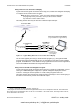
All other Com
N
av autopilots require the use of an optional ComNav Sine-Cosine Interface
Box (PN 21010004), with matching interface cable (PN 31110023 or 31110051), to use them
with a Vector G2.
See the instructions included with the Sine-Cosine Box for wiring and setup information.
Note that the G2’s Port B RS-422 wires are the ones to be connected to the Convertor.
Interfacing to a ComNav Navigator G2 Display System
See Figure 12. Wiring of the Navigator G2 is fully described in the Navigator G2’s Installation
& Operation manual. Note that there is some flexibility in how the wiring between the Vector
& the Navigator can be arranged, since part of the function of the Navigator’s Distribution Unit
is to be a simple, convenient “terminal strip” for the G2.
www.busse-yachtshop.de | info@busse-yachtshop.de