
Operating Instructions and Installation Instructions


ComNav Vector G2 & G2B Installation & Operation Installation
Document PN 29010078 V2.0 - 24 -
DRAFT #3 – 29 May 2009
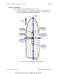
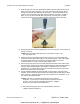
4) Route the free end of the G2’s power/data cable through the centre hole in the pole
base, from the top side of the base. Then route it down through the pole, and on
through any surfaces &/or bulkheads (as necessary) – as far as required into the
vessel. Leave some slack in the cable, below the bottom of the pole – enough to
allow you to move the connected cable a short ways out of the pole, for easier
removal of the G2 from the pole &/or pole base, should that ever be necessary.
Figure 10 – Pole Base with Cable
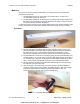
5) Thread the pole base onto the threaded pole, four to five full turns. Do not tighten up
the jam nut just yet.
Caution! Do not bottom out the pole base on the threaded mount. This
can damage the base.
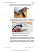
6) Align the keyway in the cable’s plug connector to the key in the G2’s data/power
connector, and then press them together, fully-seating the plug. Align, then engage
& rotate the cable connector’s locking ring (clockwise rotation to lock, and
counter-clockwise to un-lock), until you feel a definite “click”.
7) There are two pegs on the top of the base that mate with holes on the bottom of the
G2’s enclosure. Holding the enclosure in approximately the final orientation desired,
rotate the pole base & nut/washer combination so that the base is in the same
orientation (i.e., so that the base’s pegs can mate with the enclosure’s holes), then
press the enclosure down onto the base.
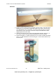
8) Use the supplied TORX bit to fasten the base to the enclosure, using the screws
supplied. These screws self-tap a thread in the matching blind screw holes (6 holes)
of the enclosure. Fasten the screws firmly, but be careful not to over-tighten, or you
may strip the self-tapped threads.
Caution! The base is not intended to be removed & re-fastened
frequently. If you remove & re-fasten the base from/to the enclosure
too often, you may strip the self-tapped hole threads. Stripped
threads are not covered under the Warranty!
L The pole mounting option does not meet IEC 60945, section 8.7
(“ability to withstand vibration”).
www.busse-yachtshop.de | info@busse-yachtshop.de