
Operating Instructions and Installation Instructions


ComNav Vector G2 & G2B Installation & Operation Installation
Document PN 29010078 V2.0 - 22 -
DRAFT #3 – 29 May 2009
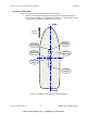
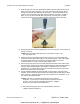
5) There are two pegs on the top of the base that mate with holes on the bottom of the
G2’s enclosure. Match the pegs to the holes, then press the base onto the
enclosure.
Figure 6 – Alignment Pegs
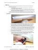
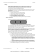
6) Use the supplied TORX bit to fasten the base to the enclosure, using the screws
supplied. These screws self-tap a thread in the matching blind screw holes (6 holes)
of the enclosure. Fasten the screws firmly, but be careful not to over-tighten, or you
may strip the self-tapped threads.
Figure 7 – Fastening the Fixed Base
Caution! The base is not intended to be removed & re-fastened
frequently. If you remove & re-fasten the base from/to the
enclosure too often, you may strip the self-tapped hole threads.
Stripped threads are not covered under the Warranty!
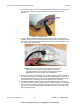
7) Route the free end of the G2’s cable, from the location where you are mounting the
G2, along (or through) the mounting surface &/or any bulkheads (as necessary), as
far as required into the vessel. Leave enough slack to allow removal of the G2 from
the fixed base from the mounting surface, should that ever be necessary.
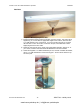
8) Install the fixed base on the flat surface, using four suitable screws or fasteners of
your choice (ComNav recommends that they be corrosion-resistant). Do not tighten
down the base-to-surface screws all the way just yet; leave them just loose enough
so that you can swivel the base, within the slotted holes, when you are doing final
alignment (see page 25).
www.busse-yachtshop.de | info@busse-yachtshop.de