Vector G2 & G2B GPS Compasses (Third Generation) Installation & Operation Manual COMPLIES WITH CE REGULATIONS PN 29010078 V2.0 Draft #3 www.busse-yachtshop.de | info@busse-yachtshop.
www.busse-yachtshop.de | info@busse-yachtshop.
ComNav Vector G2 & G2B Installation & Operation Welcome Congratulations on your purchase of a ComNav Marine Vector G2 or Vector G2B GPS Compass! At ComNav, we are dedicated to reliability & quality in all our products, and the Vectors are a good example of that. We promise to do our best to ensure your satisfaction with your new Vector GPS Compass. ComNav Marine Ltd.
ComNav Vector G2 & G2B Installation & Operation Document History Revision Date 1R0 -1R2 01 March 2006 through 07 July 2006 1R3 By Description DC, et al • first release • 1R1 & 1R2: minor edits based on user feedback 31 May 2007 DTO • added G2B & second-generation information • reformatted to new template 1R4 13 June 2007 DTO • added instructions on Baud rate settings for use with ComNav autopilots • added some more information on configuration options • moved the DGPS configuration descripti
ComNav Vector G2 & G2B Installation & Operation About this Manual This manual provides essential information for the safe and reliable operation of the ComNav Vector G2 GPS Compass. You are urged to read this manual in its entirety before you use your GPS Compass for the first time, and to keep it handy until you become thoroughly familiar with the operation of the compass. Note: most of the information in this manual applies to both models of the Vector G2 GPS Compasses: the Vector G2 and the Vector G2B.
ComNav Vector G2 & G2B Installation & Operation Document PN 29010078 V2.0 -4- DRAFT #3 – 29 May 2009 www.busse-yachtshop.de | info@busse-yachtshop.
ComNav Vector G2 & G2B Installation & Operation Table of Contents Table of Contents Welcome___________________________________________________________________________1 Warranty Notice ......................................................................................................................................................... 1 General Notice ...........................................................................................................................................................
ComNav Vector G2 & G2B Installation & Operation Table of Contents Interfacing to a PC............................................................................................................................................32 PC COM Ports..............................................................................................................................................32 D Connector Pinouts .........................................................................................................
ComNav Vector G2 & G2B Installation & Operation Table of Contents Care & Maintenance ________________________________________________________________65 Protection of Wires and Cabling............................................................................................................................... 65 Periodic Checks ....................................................................................................................................................... 65 General Precautions .....
ComNav Vector G2 & G2B Installation & Operation Figures & Tables List of Figures Figure 1 – Typical G2 System ....................................................................................................................................13 Figure 2 – Heading & Pitch Installation (viewed from above) .....................................................................................19 Figure 3 – Heading & Roll Installation (viewed from above)...........................................................
ComNav Vector G2 & G2B Installation & Operation Figures & Tables List of Tables Table 1 – Standard Cable Lengths ............................................................................................................................26 Table 2 – Cable Colour Codes...................................................................................................................................27 Table 3 – Commander P2 Connection Details ..................................................................
ComNav Vector G2 & G2B Installation & Operation Document PN 29010078 V2.0 - 10 - DRAFT #3 – 29 May 2009 www.busse-yachtshop.de | info@busse-yachtshop.
ComNav Vector G2 & G2B Installation & Operation Introduction Document PN 29010078 V2.0 - 11 - DRAFT #3 – 29 May 2009 www.busse-yachtshop.de | info@busse-yachtshop.
ComNav Vector G2 & G2B Installation & Operation Document PN 29010078 V2.0 - 12 - DRAFT #3 – 29 May 2009 www.busse-yachtshop.de | info@busse-yachtshop.
ComNav Vector G2 & G2B Installation & Operation Introduction Overview The Vector G2 GPS Compass is a state-of-the-art electronic navigation data device. It is capable of providing highly accurate, high-precision position and heading data to a wide variety of marine Navigation equipment, such as autopilots, sonar, radar, chartplotters, AIS receivers & transponders, and many other types of marine devices & systems.
ComNav Vector G2 & G2B Installation & Operation Introduction There are two models available – the Vector G2 and the Vector G2B; they are identical, except in their Differential GPS (DGPS) correction features: • The Vector G2 can obtain DGPS information from many Space-Based Augmentation System (SBAS) sources (in areas where compatible ones are available & operational), including WAAS, EGNOS, MSAS, SNAS, GAGAN and others. The Vector G2 can also accept DGPS information from an external data source.
ComNav Vector G2 & G2B Installation & Operation Installation Document PN 29010078 V2.0 - 15 - DRAFT #3 – 29 May 2009 www.busse-yachtshop.de | info@busse-yachtshop.
ComNav Vector G2 & G2B Installation & Operation Document PN 29010078 V2.0 - 16 - DRAFT #3 – 29 May 2009 www.busse-yachtshop.de | info@busse-yachtshop.
ComNav Vector G2 & G2B Installation & Operation Installation Installation Please refer to the Warranty Information section of this manual before proceeding with installation of the Vector G2. Tools Required General-purpose tools such as a portable drill, pliers, wire cutters, screwdrivers, wire, mounting bolts and wrenches will be required. An accurate voltmeter or multi-meter would also be useful.
ComNav Vector G2 & G2B Installation & Operation Installation GPS Reception Considerations The following points relating to GPS reception must be considered: • • Mount the G2’s enclosure as high as possible, considering maintenance and accessibility. Ensure that there is an unobstructed as possible “view” of the sky available to the unit, to avoid blocking the RF signals from the GPS satellites.
ComNav Vector G2 & G2B Installation & Operation Installation Location & Orientation There are two primary mounting orientations for the Vector G2: • Normally, the G2 will be mounted so that the longitudinal axis is aligned with the vessel’s fore-aft centreline, or is parallel to that centreline. In this orientation, the G2 can output both the Heading and the Pitch of the vessel.
ComNav Vector G2 & G2B Installation & Operation • Installation If you wish, you can instead install the G2 perpendicular to the vessel’s fore-aft centreline, i.e., on (or parallel to) the athwartships centreline. In this orientation, the G2 can output both the Heading and the Roll of the vessel.
ComNav Vector G2 & G2B Installation & Operation Installation Mounting The Vector G2 can be mounted on a fixed base, or on a pole; parts for both options are provided with system kits: • The fixed base option is for mounting the G2 on a flat surface – a cabin roof, a mounting plate on the mast, and so on.
ComNav Vector G2 & G2B Installation & Operation Installation 5) There are two pegs on the top of the base that mate with holes on the bottom of the G2’s enclosure. Match the pegs to the holes, then press the base onto the enclosure. Figure 6 – Alignment Pegs 6) Use the supplied TORX bit to fasten the base to the enclosure, using the screws supplied. These screws self-tap a thread in the matching blind screw holes (6 holes) of the enclosure.
ComNav Vector G2 & G2B Installation & Operation Installation Pole Base Figure 8 – Mounting using the Pole Base 1) Install a threaded mounting pole at the location you have chosen. The pole must be supplied by you; it must have an appropriate height for the location, and must have 1-14-UNS threads on one or both ends. If you are mounting the pole on a surface, drill & de-burr a hole in the surface, centered in the pole, with a diameter at least slightly larger than the G2’s cable.
ComNav Vector G2 & G2B Installation & Operation Installation 4) Route the free end of the G2’s power/data cable through the centre hole in the pole base, from the top side of the base. Then route it down through the pole, and on through any surfaces &/or bulkheads (as necessary) – as far as required into the vessel.
ComNav Vector G2 & G2B Installation & Operation Installation Alignment Adjust the orientation of the Vector G2 as necessary, and then secure it when complete: • • The four slots in the fixed base allow for several degrees of adjustment of the orientation of the enclosure. When you have obtained the desired orientation, tighten down the fasteners that you used in the slots securely. The pole base can be rotated freely on the pole, as long as the jam nut is loose.
ComNav Vector G2 & G2B Installation & Operation Installation Wiring A single cable, included with the Vector G2, supplies power to it, and also carries NMEA 0183 data & control signals from & to it. The G2 end of the cable is an environmentally sealed, mechanically-keyed/locking connector; the other end is un-terminated, and requires field stripping and tinning. The cable should be wired to your vessel’s autopilot, and/or other equipment of your choice that can use NMEA 0183 data.
ComNav Vector G2 & G2B Installation & Operation Installation Cable Colour Codes Cable Marking: 051-0157-002 (15 metres), 051-0158-001 (30 metres) Wire Colour Signal Description Red 1 n/a Power Input Black 1 n/a Power Ground Blue RS-232, Tx Port A Transmit Black, Blue stripe RS-232, Rx Port A Receive Black, Green stripe RS-422, ‘A’ Green RS-422, ‘B’ Port A Transmit Brown RS-232, Tx Port B Transmit Black, Brown stripe RS-232, Rx Port B Receive Yellow, Black stripe RS-422, ‘A’ Yel
ComNav Vector G2 & G2B Installation & Operation Installation Data Connections (Autopilot, GPS Display, Chartplotter, PC, etc.) There are a number of ways to make the data connections required between the Vector G2 and other equipment on the vessel. See Figure 12, Figure 14 and Figure 15 for examples: • The G2 is typically used with a ComNav Autopilot System (e.g., Commander P2, Admiral P3, 2001, 5001, etc.
ComNav Vector G2 & G2B Installation & Operation Installation RS-232 The only electrical standard specified in NMEA 0183 is RS-422. However, it is common for non-marine equipment to be able to accept NMEA-formatted data – not at RS-422 levels, but only at RS-232 levels; for example, the “COM port” on a PC is always at RS-232 levels. Such equipment (often described as being “NMEA compatible”) will require using one or both of the G2’s RS-232 outputs.
ComNav Vector G2 & G2B Installation & Operation Installation Interfacing to a ComNav Autopilot Commander P2 or Admiral P3 Figure 12 shows the typical connections used with a ComNav Commander P2 Autopilot System (an Admiral P3 would be wired identically), a ComNav Navigator G2 GPS Compass Display System, and a generic Chartplotter or other type of Navigation System.
ComNav Vector G2 & G2B Installation & Operation Installation Vector G2 or G2B Power Switch Fuse or Breaker RED (18 AWG) BLACK (18 AWG) - Ship’s Battery + 11 – 36 VDC Alarm Contacts WHITE & WHITE w/ RED STRIPE Cut off & tape back Shield Drain wire Alarm System Navigation System Controller or Display (Chartplotter, Radar, etc.
ComNav Vector G2 & G2B Installation & Operation Installation Interfacing to a PC PC COM Ports PC serial ports – commonly referred to as “COM ports” – always use RS-232 signal levels, and so the only possible direct connection to the Vector G2 is via the G2’s RS-232 signals. L If it is necessary to connect a PC to any RS-422 signals (for example, when the PC is being used to run a Navigation program, which sends steering commands to an NMEA 0183 autopilot – i.e.
ComNav Vector G2 & G2B Installation & Operation Installation DE9 Connectors To connect either of the G2’s RS-232 ports to a PC serial port (or to the DE9-P end of a USB-to-Serial adapter), connect the wires to a DE9 female connector (a “socket type”, aka DB9-S) as follows: DE9 Pin Wire Color G2 Signal COM Port Signal 2 Blue Port A Transmit data Receive Data 3 Black w/ Blue Stripe Port A Receive data Transmit Data 2L Brown Port B Transmit data Receive Data 3L Black w/ Brown Stripe Port B
ComNav Vector G2 & G2B Installation & Operation Installation Using a PC for Vector G2 Control & Display Figure 14 shows the typical connections when using a PC, instead of a Navigator G2 Display, to configure the G2, and/or monitor its status. Note: the PC is not necessary 6, if the G2’s factory-default configuration (see page 46) meets your needs, and if you do not wish to monitor any of the G2’s various status values. This wiring scheme uses only the G2’s Port A RS-232 output and input.
ComNav Vector G2 & G2B Installation & Operation Installation Vector G2 or G2B PC for Navigation Control & Display (using suitable software) PC COM Port n* Port A (RS-232) Signal & Pin # BLUE BLACK w/ BLUE STRIPE GREY Tx Rx 2 Rx Tx 3 RS-232 Signal Ground Use one or the other wire pair into the Convertor inputs From other NMEA equipment D-Type 9 pin Female Connector (user-supplied) 5 * COM Ports used for G2 & NMEA connections are user-selected, but MUST be different NMEA 0183 RS-232 Convert
ComNav Vector G2 & G2B Installation & Operation Installation The PC would typically be running a Navigation program (e.g., programs from Fugawi™, Jeppesen®/Nobeltec®, Rose Point Navigation, or similar), replacing the Navigation control functions of (or as a backup to) the Chartplotter.
ComNav Vector G2 & G2B Installation & Operation Operation Document PN 29010078 V2.0 - 37 - DRAFT #3 – 29 May 2009 www.busse-yachtshop.de | info@busse-yachtshop.
ComNav Vector G2 & G2B Installation & Operation Document PN 29010078 V2.0 - 38 - DRAFT #3 – 29 May 2009 www.busse-yachtshop.de | info@busse-yachtshop.
ComNav Vector G2/G2B Installation & Operation Operation Operation The Vector G2 GPS Compass provides accurate, reliable, high-precision position and heading data. It is intended to be used with a wide variety of marine Navigation equipment.
ComNav Vector G2/G2B Installation & Operation Operation GPS Signal Reception & Processing The G2 contains a high performance GPS “engine”, containing twin GPS receivers and two multipath-resistant antennas. One antenna is designated as the Primary GPS antenna, while the other is designated as the Secondary. In the G2B, there is also a Radiobeacon antenna (located with the Primary GPS antenna).
ComNav Vector G2/G2B Installation & Operation Operation The Vector G2B can also use: • Conventional terrestrial DGPS Radiobeacon signals. Marine authorities in many countries around the world have installed networks of Radiobeacon transmitters, which broadcast DGPS corrections valid in the vicinity of each such transmitter. As well, there is an increasing number of DGPS Radiobeacon transmitters located well inland, which are usable for non-marine applications.
ComNav Vector G2/G2B Installation & Operation Operation Moving Base Station RTK The technique of computing the location of the Secondary GPS antenna with respect to the Primary antenna, when the Primary antenna is moving, is often referred to as Moving Base Station Real-Time Kinematic (or as Moving-base-station RTK, or just RTK).
ComNav Vector G2/G2B Installation & Operation Operation Supplemental Sensors Integrated inside the Vector G2’s enclosure, on the main printed circuit board, are two sensors. One sensor is an accelerometer, which measures the tilt of the G2’s enclosure; the other sensor is a solid-state gyro, which measures the rate of turn. Both sensors are enabled by default. Each sensor may be turned on or off individually; however, the full functionality of the G2 is realized only when both are used.
ComNav Vector G2/G2B Installation & Operation Operation Gyro-aided RTK The Vector G2’s internal gyro offers several benefits. It will shorten reacquisition times when the G2’s heading computation is stopped due to momentary obstruction of GPS satellite signals, by reducing the search volume required for solution of the RTK, after obstruction of the signals ends.
ComNav Vector G2/G2B Installation & Operation Operation Normal Operation Once the Vector G2 has successfully acquired a sufficient number of GPS signals, of high enough quality, it begins to generate navigational data – position, heading, speed and so on. It’s up to you what you do with that data, of course! The G2 is configured at the factory with a specific set of output data settings … enabled output data “sentences”, update rates and Baud rates. All those are described in this section.
ComNav Vector G2/G2B Installation & Operation Operation Output Data Formats There are three formats that the Vector G2 can output data in: the NMEA 0183 Standard’s format, a proprietary format, and a binary format. For full details on the NMEA sentences, please refer to the NMEA 0183 Standard. For details on the G2’s specific capabilities (fields, format, etc.) in the NMEA 0183 sentences, please refer to the GPS Technical Reference.
ComNav Vector G2/G2B Installation & Operation Operation Proprietary Output A number of NMEA-like 11 proprietary output sentences are available on the Vector G2. Only the HPR sentence is enabled when the G2 is shipped from the factory; it is set to a 1 Hz update rate, on Port A. All the others are disabled, and so are indicated below with an X. Maximum output rates are shown in the far right column, for convenience. To make changes, see pages 51 and 52 (and 53, for a G2B).
ComNav Vector G2/G2B Installation & Operation Operation Baud Rate All ComNav autopilots (and all marine equipment which is compliant to the NMEA 0183 Standard) communicate at 4800 Baud, for both input & output 12. But, although the NMEA Standard specifies 4800 Baud 13, it is common for “NMEA compatible” equipment to be able to work at higher speeds (especially at RS-232 levels).
ComNav Vector G2/G2B Installation & Operation Operation Changing the Configuration You may change the factory-default configuration of the Vector G2, if you wish! • Many other output sentences can be enabled, and/or the factory-default ones disabled, to suit the requirements of any specific installation. • The output update rate of each enabled sentence may be changed as required. – If a given sentence is enabled on both ports, the output rate on each port may the same, or different, if desired.
ComNav Vector G2/G2B Installation & Operation Operation Using PocketMAX PC Full instructions are in the PocketMAX User Manual. The system must be wired as shown in Figure 14 or Figure 15. Note: PocketMAX PC may not always run properly on some PCs. It has been known to hang up, and/or crash the PC (especially on an older, slower PC), and/or leave the G2 in an invalid state. ComNav recommends that you use PocketMAX only on a fairly new PC, with a fast CPU, lots of RAM, and “standard” COM ports.
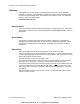
ComNav Vector G2/G2B Installation & Operation Operation Configuration Commands The NMEA-like input sentences in the following tables are commands that can be used to configure the Vector G2. These commands must be sent to the G2 on the RS-232 Receive signal wire of Port A. All commands must end with an END OF LINE sequence (i.e., ASCII codes). Most commands may be entered in upper, lower or mixed case. Some of the commands have optional parameters (shown in square brackets in the tables).
ComNav Vector G2/G2B Installation & Operation Operation L Caution L Many of the commands in the tables below will affect the performance of the Vector G2. Improper settings may result in degradation of system output, which can affect the overall safety of the vessel and personnel. Command Rate (Hz) Sentence $JASC,GPDTM,rate[,OTHER] GPDTM 0, 0.2, 1, 5 or 10 $JASC,GPGGA,rate[,OTHER] GPGGA 0, 0.2, 1, 5 or 10 $JASC,GPGLL,rate[,OTHER] GPGLL 0, 0.
ComNav Vector G2/G2B Installation & Operation Command Operation Rate (Hz) Data in Sentence $JBIN,1,rate GPS Position 0, 0.
ComNav Vector G2/G2B Installation & Operation Command $JATT,COGTAU,cogtau Operation Range (seconds) Action & Time Constant Affected $JTAU,COG,cogtau Query or Set the Course-Over-Ground Constant cogtau = 0.0 to 200.0 $JATT,HTAU.htau Query or Set the Heading Constant htau = 0.0 to 3600.0 $JATT,HRTAU,hrtau Query or Set the Rate of Turn Constant hrtau = 0.0 to 3600.0 $JATT,PTAU,ptau Query or Set the Pitch (or Roll) Constant ptau = 0.0 to 3600.0 Query or Set the Speed Constant spdtau = 0.
ComNav Vector G2/G2B Installation & Operation Operation Command $J4STRING,BAUD[,OTHER] Description • Enable GPGGA, GPGSA, GPVTG & GPZDA at 1 Hz • Set both ports Baud rate to BAUD (4800, 9600, 19200, 38400) • Do a $JSAVE (see Table 16) L $JAGE,age Set the Differential Age Timeout • age = 6 to 8100 seconds $JATT,COAST[,NO/YES] 1 Query or Enable/Disable the xxxxx $JATT,COGAID[,NO/YES] Query or Enable/Disable the xxxxx $JATT,EXACT[,NO/YES] Query or Enable/Disable the xxxxx $JATT,HDMTRUE[,NO/YES] Q
ComNav Vector G2/G2B Installation & Operation Operation Command Description $JATT,CSEP Query the current computed antenna separation (Should always return 0.500 ± 0.010 metres) $JATT,MSEP[,sep] Query or Set the actual separation between the antennae L In the Vector G2 & G2B, the physical antenna separation is fixed at 0.5 metres – so this command should only be used to check that the MSEP value is set correctly (to 0.
ComNav Vector G2/G2B Installation & Operation Operation Other Commands The commands in Table 8 through Table 16 above are all the ones typically used in marine applications of the G2. There are several other commands which Hemisphere’s Crescent chipset supports. Most of these other commands are documented in the GPS Technical Reference 18.
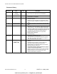
ComNav Vector G2/G2B Installation & Operation Operation Customising & Fine-tuning the Configuration There are a number of situations where you might want to change the Vector G2’s factory-default configuration settings in ways other than simply enabling or disabling the specific sentences that your system requires, or changing the update rates of the enabled sentence(s). Roll Alignment One common situation is if you have mounted the G2 athwartships.
ComNav Vector G2/G2B Installation & Operation Operation Disabling the Tilt Sensor The Vector G2’s tilt sensor is enabled by default. You can turn the tilt sensor off with a $JATT,TILTAID,0 command. The only time you might need to do that is when troubleshooting, to ensure the GPS receiver is working properly. Re-calibrating the Tilt Sensor The tilt sensor is pre-calibrated at the factory.
ComNav Vector G2/G2B Installation & Operation Operation Measurement Time Constant Sentences Affected Course Over Ground COGTAU $GPVTG Heading HTAU $GPHDT, HDG, HDM Rate Of Turn HRTAU $GPROT Pitch (or Roll) PTAU $PSAT,HPR Speed SPDTAU $GPRMC, VTG, BIN 1 Usage • If the vessel is resistant to quick changes in its motion, increase it. • If vessel does not turn quickly, increase it. • If vessel does not turn quickly, increase it. • If vessel does not pitch (roll) quickly, increase it.
ComNav Vector G2/G2B Installation & Operation Operation DGPS Source The factory-default DGPS correction source in the Vector G2 is NONE; the default source in the G2B is BEACON. This may be changed using the $JDIFF command (see Table 15 on page 55). To select SBAS signals for the DGPS data, use a $JDIFF,WAAS command. However, this should only be done in areas where the visible SBAS satellites are sending data that is valid for the area where the G2 or G2B is currently located.
ComNav Vector G2/G2B Installation & Operation Operation Figure 20 – Data Bandwidth Estimation Document PN 29010078 V2.0 - 62 - DRAFT #3 – 29 May 2009 www.busse-yachtshop.de | info@busse-yachtshop.
ComNav Vector G2 & G2B Installation & Operation Care & Maintenance Document PN 29010078 V2.0 - 63 - DRAFT #3 – 29 May 2009 www.busse-yachtshop.de | info@busse-yachtshop.
ComNav Vector G2 & G2B Installation & Operation Document PN 29010078 V2.0 - 64 - DRAFT #3 – 29 May 2009 www.busse-yachtshop.de | info@busse-yachtshop.
ComNav Vector G2 & G2B Installation & Operation Care & Maintenance Care & Maintenance The Vector G2 & G2B GPS Compasses haves been designed to provide many years of reliable service. The following care and maintenance tips will help to ensure the longevity of your Vector. Protection of Wires and Cabling After installation, ensure that the system components are securely mounted and will not shake loose due to the vibrations that can be expected in a marine vessel.
ComNav Vector G2 & G2B Installation & Operation Document PN 29010078 V2.0 - 66 - DRAFT #3 – 29 May 2009 www.busse-yachtshop.de | info@busse-yachtshop.
ComNav Vector G2 & G2B Installation & Operation Appendices Document PN 29010078 V2.0 - 67 - DRAFT #3 – 29 May 2009 www.busse-yachtshop.de | info@busse-yachtshop.
ComNav Vector G2 & G2B Installation & Operation Document PN 29010078 V2.0 - 68 - DRAFT #3 – 29 May 2009 www.busse-yachtshop.de | info@busse-yachtshop.
ComNav Vector G2 & G2B Installation & Operation Appendices Appendices Appendix 1 Specifications GPS Receiver Parameter Specification • Twin receivers, 0.5m antenna separation • L1, C/A code, with carrier phase smoothing • 1.575 GHz carrier frequency Receiver Type Channels Two x 12, parallel tracking (Two x 10 channels when tracking SBAS) Update Rate • position: adjustable, 20 Hz max • heading: adjustable, 20 Hz max Horizontal Accuracy 1 • < 1 m RMS when using DGPS corrections • < 2.
ComNav Vector G2 & G2B Installation & Operation Appendices System Interface Parameter Specification • RS-232 Serial: o 2 full-duplex • RS-422 Serial: o 2 half-duplex, output only o same data as output on RS-232 • all ports optically isolated Ports Baud Rate 4800 (default), 9600, 19200 and 38400 Data Output Protocol NMEA 0183, proprietary ASCII (Crescent) & proprietary binary (see Table 6 & Table 7) Data Input Protocol NMEA-like (see Table 8 - Table 10) Timing Output 1 1 pps, 50 ns accuracy (HCM
ComNav Vector G2 & G2B Installation & Operation Appendices Appendix 2 Setting Up & Using HyperTerminal This section describes the basic procedures for using HyperTerminal with a Vector G2. • • Most of the screen shots and examples of typical data & commands in this section were taken while running the standard HyperTerminal 21 program on a newer PC (running a Core2 Quad CPU, Windows XP Pro 32-bit SP3, and an LCD display at 1600 x 1200).
ComNav Vector G2 & G2B Installation & Operation • Appendices Choose the COM Port which is connected to the G2’s Port A: Figure 22 – COM Port Selection Dialog Box • Set up the COM port’s Baud rate, serial format (8-N-1), and flow control: Figure 23 – COM Port Settings Document PN 29010078 V2.0 - 72 - DRAFT #3 – 29 May 2009 www.busse-yachtshop.de | info@busse-yachtshop.
ComNav Vector G2 & G2B Installation & Operation • Appendices The new connection’s communication session will then start – but HyperTerminal is not fully set up yet for use with the G2, so click on the Disconnect button, to stop the session: Figure 24 – Disconnect Button • Figure 25 – Call Button Set up the remaining COM port parameters; select File ⇒ Properties ⇒ Settings: Figure 26 – COM Port Properties Dialog Box, Settings Tab Document PN 29010078 V2.0 - 73 - DRAFT #3 – 29 May 2009 www.
ComNav Vector G2 & G2B Installation & Operation – Appendices Click on the ASCII Setup button: Figure 27 – COM Port ASCII Setup Dialog Box Note: you may find that a Line Delay longer or shorter than 10 msec will be needed on your PC; you may also need to set a non-zero Character Delay. – • The other buttons on the Settings Tab do not need to be clicked, since the default parameter values on those dialogs are fine. Exit the File ⇒ Properties ⇒ Settings dialog (click on the appropriate OK buttons).
ComNav Vector G2 & G2B Installation & Operation Appendices Use the New Connection to the G2 Now that you have your connection set up, you can use it: • • • • Re-start the HyperTerminal session: click on the Call button (see Figure 25). If you want to monitor both of the G2’s ports, start another HyperTerminal session, setting it up the same as above, but on another COM port (COM 6, for the G2’s Port B, in the screen shots here).
ComNav Vector G2 & G2B Installation & Operation Appendices Figure 28 – A Typical Two-session Screen Document PN 29010078 V2.0 - 76 - DRAFT #3 – 29 May 2009 www.busse-yachtshop.de | info@busse-yachtshop.
ComNav Vector G2 & G2B Installation & Operation Appendices Monitoring the G2 This is a more detailed look at a typical HyperTerminal session on Port A, after about an hour and a half of operation (on the laptop): Figure 29 – Typical Port A Session This is a more detailed look at the matching session on Port B: Figure 30 – Typical Port B Session Document PN 29010078 V2.0 - 77 - DRAFT #3 – 29 May 2009 www.busse-yachtshop.de | info@busse-yachtshop.
ComNav Vector G2 & G2B Installation & Operation Appendices Capturing Data Output from the G2 One of the problems with using HyperTerminal is that it’s hard to watch individual sentences, or inspect them carefully – because the data keeps coming out of the G2, so the text in the HyperTerminal’s “screen” area is constantly changing, as new data comes in and the older data scrolls up (& eventually off) the active display area.
ComNav Vector G2 & G2B Installation & Operation Appendices This is 5 seconds (i.e., one full sequence of all the factory-default enabled sentences) of typical output from Port A, captured into a text file (see also the examples on page 85): $GPHDT,264.09,T*0C $GPROT,-2.4,A*1A $GPHDM,246.37,M*01 $GPHDG,246.37,0.00,E,17.72,E*59 $PSAT,HPR,232346.00,264.09,6.88,,N*31 $GPGGA,232346.00,4911.30205,N,12304.50987,W,2,05,2.5,4.3,M,-17.6,M,5.8,0304*7D $GPGLL,4911.30205,N,12304.50987,W,232346.00,A,D*72 $GPVTG,1.
ComNav Vector G2 & G2B Installation & Operation Appendices Sending Commands to the G2 Another problem when using HyperTerminal with a G2 is that it’s hard to simply “type” commands to the G2. That’s because HyperTerminal is a “dumb terminal” program – it depends on the device it is “talking to” (the G2, in this case) for “editing user input” … hit a key on the keyboard, and that character immediately gets sent out to the G2. But the G2 is does not have an “input editor” function (i.e.
ComNav Vector G2 & G2B Installation & Operation Appendices Some sample script files we use when working with the G2 at ComNav are shown below. Please feel free to use them in your own work with the G2! For a description of the individual commands here, see Table 8 thru Table 13, and the GPS Technical Reference.
ComNav Vector G2 & G2B Installation & Operation Appendices 4) Query DGPS.txt – shows the current status of the SBAS functions 26: $JASC,D1,1 Ì $JASC,D1,0 5) Query Beacon.txt – shows the current status of the Beacon receiver (in the G2B only): $PCSI,1,1 $PCSI,2,1 $PCSI,1,0 $PCSI,2,0 6) Query Tilt.txt – shows the current readings from the tilt sensor: $JASC,INTLT,1 Ì $JASC,INTLT,0 7) Query Satelites.
ComNav Vector G2 & G2B Installation & Operation Appendices 9) Set ComNav Defaults (Port B).txt – configures the G2 with the factory defaults: 2nd & 3rd Generation 1st Generation $JOFF,OTHER $PCSI,1,0,OTHER $PCSI,2,0,OTHER $JASC,GPHDM,10,OTHER $JASC,GPHDT,10,OTHER $JASC,GPVTG,1,OTHER $JOFF,OTHER $PCSI,1,0,OTHER $PCSI,2,0,OTHER $JASC,HCHDM,5,OTHER $JASC,HEHDT,5,OTHER $JASC,HEROT,5,OTHER $JASC,GPVTG,1,OTHER 10) Set DGPS Beacon.
ComNav Vector G2 & G2B Installation & Operation Appendices Example Responses The following are examples of the G2’s typical responses to some of the scripts above, and to single commands entered manually. 1) This is the output from a Query All script (all normal output had been disabled before this, with an All Off script – see page 81): $>JT,SX2a $>JI,390639,1,7,24012008,01/01/1900,01/01/3000,1.
ComNav Vector G2 & G2B Installation & Operation Appendices 6) Here is the G2’s reply when you enter a $JSAVE command: (normal data output … whatever is currently configured) ... ... $> Saving Configuration. Please Wait... ... ... (normal data output continues for ~5 seconds) ... ... $> Save Complete ... ...
ComNav Vector G2 & G2B Installation & Operation • Appendices after a few more seconds, the ZDA & HPR sentences begin to have valid time/date data, and GSV appears: $GPHDT,,T*1B $GPROT,,V*08 $GPHDM,,M*1B $GPHDG,,,E,,E*70 $PSAT,HPR,232248.78,,,,*70 $GPGGA,,,,,,0,,,,M,,M,,*66 $GPGLL,,,,,,V,N*64 $GPVTG,,T,,M,,N,,K,N*2C $GPZDA,232248.78,14,05,2009,00,00*6F $GPHDT,,T*1B $GPROT,,V*08 $GPHDM,,M*1B $GPHDG,,,E,,E*70 $PSAT,HPR,232249.
ComNav Vector G2 & G2B Installation & Operation Appendices 8) Here is a typical power-on sequence from Port B (captured simultaneously with the Port A sequence above): • the first second is all Null data: $GPHDT,,T*1B $GPHDM,,M*1B $GPHDT,,T*1B $GPHDM,,M*1B $GPHDT,,T*1B $GPHDM,,M*1B $GPHDT,,T*1B $GPHDM,,M*1B $GPHDT,,T*1B $GPHDM,,M*1B $GPHDT,,T*1B $GPHDM,,M*1B $GPHDT,,T*1B $GPHDM,,M*1B $GPHDT,,T*1B $GPHDM,,M*1B $GPHDT,,T*1B $GPHDM,,M*1B $GPHDT,,T*1B $GPHDM,,M*1B $GPVTG,,T,,M,,N,,K,N*2C • after ~35 second
ComNav Vector G2 & G2B Installation & Operation Document PN 29010078 V2.0 Appendices - 88 - DRAFT #3 – 29 May 2009 www.busse-yachtshop.de | info@busse-yachtshop.
ComNav Vector G2 & G2B Installation & Operation Appendices Appendix 3 Vector Model Generations To date, there have been 3 generations of the Vector G2 & G2B GPS Compasses. All are named “Vector G2” (or “Vector G2B”), and all use the same ComNav part numbers; for example, PN 11210001 is a Vector G2 with 15m cable & mounting brackets, irrespective of generation.
ComNav Vector G2 & G2B Installation & Operation • Appendices The significant differences in features & operating specifications between the three generations of ComNav Vector G2 & G2B GPS Compasses are listed below. Generation Feature First Second Third Operating Voltage 8 – 40 VDC 10 – 36 VDC 11 – 36 VDC Power Consumption < 4.5 W <5W < 4.
ComNav Vector G2 & G2B Installation & Operation Appendices Differences between Cables There have been five different standard cables supplied with ComNav Vector G2 & G2B GPS Compasses, across the three generations – three 15 metre cables, and two 30 metre cables. The main difference between the various cables is in the colour-coding of the wires. The wire colour codes depend on the cable’s “marking” number (which is in fact the Hemisphere GPS part number) on the cable’s label.
ComNav Vector G2 & G2B Installation & Operation Appendices Cable Usage • For the 15 metre cable supplied on the first-generation G2s (marking 051-0063-003), there are several black coloured signal wires, each carrying a different signal – which can be very confusing. To help prevent wiring errors caused by “many black wires”, all the wires in this cable are twisted in pairs, with each black wire paired with its respective non-black coloured counterpart.
ComNav Vector G2 & G2B Installation & Operation Appendices CE COMPLIANCE This product is in compliance with the Electro-Magnetic Compatibility (EMC) standards of the European Community, and therefore bears the CE-marking, per EMC Directive 2004/108/EC It has been tested according to the applicable sections outlined under: Technical Standard IEC 60945 ed.
ComNav Vector G2 & G2B Installation & Operation Document PN 29010078 V2.0 Appendices - 94 - DRAFT #3 – 29 May 2009 www.busse-yachtshop.de | info@busse-yachtshop.
ComNav Vector G2 & G2B Installation & Operation Appendices Compass Safe Distance Certificate Document PN 29010078 V2.0 - 95 - DRAFT #3 – 29 May 2009 www.busse-yachtshop.de | info@busse-yachtshop.
ComNav Vector G2 & G2B Installation & Operation Document PN 29010078 V2.0 Appendices - 96 - DRAFT #3 – 29 May 2009 www.busse-yachtshop.de | info@busse-yachtshop.
ComNav Vector G2/G2B Installation & Operation Warranty Warranty Information Limited Warranty This Limited Warranty (the “Warranty”) covers all Vector and Navigator GPS Compass products & accessories (the “Equipment”) sold by ComNav Marine Ltd. (“ComNav”).
ComNav Vector G2/G2B Installation & Operation Warranty NO OTHER WARRANTIES THE FOREGOING WARRANTY IS EXCLUSIVE OF ALL OTHER WARRANTIES AND CONDITIONS, WHETHER WRITTEN, ORAL OR IMPLIED, ARISING BY STATUTE OR OTHERWISE, WITH RESPECT TO THE DESIGN, SALE, INSTALLATION OR USE OF THE EQUIPMENT, INCLUDING BUT NOT LIMITED TO IMPLIED WARRANTIES OR CONDITIONS OF MERCHANTABILITY AND FITNESS FOR THE ORDINARY PURPOSES FOR WHICH THE EQUIPMENT IS USED OR FITNESS FOR A PARTICULAR PURPOSE, AND ANY OTHER OBLIGATIONS ON THE
ComNav Vector G2/G2B Installation & Operation Warranty 2. If, upon examination by ComNav, the defect is determined to result from defective workmanship or material and if the defect has occurred within the warranty period set forth above, the Equipment or the defective parts thereof shall be repaired or replaced, at ComNav’s sole option, without charge, and shall be returned to the Purchaser at ComNav’s expense. Return delivery will be by the most economical means.
ComNav Vector G2/G2B Installation & Operation Document PN 29010078 V2.0 - 100 - DRAFT #3 – 29 May 2009 www.busse-yachtshop.de | info@busse-yachtshop.
ComNav Vector G2/G2B Installation & Operation Index Document PN 29010078 V2.0 - 101 - DRAFT #3 – 29 May 2009 www.busse-yachtshop.de | info@busse-yachtshop.
ComNav Vector G2/G2B Installation & Operation Document PN 29010078 V2.0 - 102 - DRAFT #3 – 29 May 2009 www.busse-yachtshop.de | info@busse-yachtshop.
ComNav Commander P2 Installation & Operation Index Index –A– –I– Acquisition Time.................................................. 39 Alignment ........................2, 20, 22, 25, 41, 58, 107 Installation....... 1, 15, 17, 19, 20, 30, 36, 50, 89, 92 –N– –B– Baud rate..2, 29, 36, 45, 48, 49, 51, 54, 55, 56, 61, 72, 83, 90 Beacon .....3, 18, 28, 41, 47, 53, 55, 61, 69, 75, 82, 83, 90 Binary ..........................................47, 51, 53, 57, 90 –C– Care & Maintenance .........................
ComNav Vector G2 & G2B Installation & Operation Document PN 29010078 V2.0 - 104 - DRAFT #3 – 29 May 2009 www.busse-yachtshop.de | info@busse-yachtshop.
ComNav Vector G2 & G2B Installation & Operation User Notes Document PN 29010078 V2.0 - 105 - DRAFT #3 – 29 May 2009 www.busse-yachtshop.de | info@busse-yachtshop.
ComNav Vector G2 & G2B Installation & Operation Document PN 29010078 V2.0 - 106 - DRAFT #3 – 29 May 2009 www.busse-yachtshop.de | info@busse-yachtshop.
ComNav Vector G2 & G2B Installation & Operation User Notes User Notes & Settings User Settings Once your Vector G2 has been installed and configured correctly, you can make a record of all the settings you have chosen, in the tables below. Port A Sentences Range GPDTM 0, 0.2, 1, 5 or 10 GPGGA 0, 0.2, 1, 5 or 10 GPGLL 0, 0.2, 1, 5, 10 or 20 GPGNS 0, 0.2, 1, 5 or 10 GPGRS 0, 0.2, 1, 5 or 10 GPGSA 0 or 1 GPGST 0 or 1 GPGSV 0 or 1 GPHDG 0, 0.2, 1, 5, 10 or 20 GPHDM 0, 0.2, 1, 5, 10 or 20 GPHDT 0, 0.
ComNav Vector G2 & G2B Installation & Operation User Notes Notes Document PN 29010078 V2.0 - 108 - DRAFT #3 – 29 May 2009 www.busse-yachtshop.de | info@busse-yachtshop.