
Operating Instructions and Installation Instructions

ComNav Navigator G2 Installation & Operation Installation
Document PN 29010081 V1.1 - 21 -
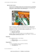
Display Head Terminals (#1 and #2)
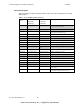
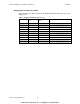
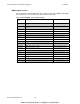
Table 2 below lists the different signals in the Display Head cable which goes out to each
Display Head.
Table 2 – Display Head Wiring and Connection
Silkscreen Label Type 1 Wire Color
Codes
Type 2 Wire Color
Codes
Description
+V Orange Orange Power to Display Head – Point 1
Shield Bare Wire Bare Wire Drain for RF Shielding
FR Brown White w/Black Stripe Data Communications Frame signal
CS Green Green Data Communications Select Signal
+V Red Red Power to Display Head – Point 2
GND Black Black Power Ground
Data Out Yellow Red w/Black Stripe Data Communications To the Display Head
Data In Violet Green w/Black Stripe Data Communications From the Display Head
Clock White White Data Communications Clock Signal
ON Blue Blue Display Head Power On Button
www.busse-yachtshop.de | info@busse-yachtshop.de