
Operating Instructions and Installation Instructions

ComNav Navigator G2 Installation & Operation Installation
Document PN 29010081 V1.1 - 19 -
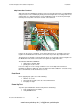
Vector G2 Terminals
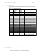
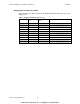
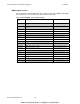
Table 1 below lists the different signals and wire codes in the cable coming from a Vector G2
GPS Compass.
Table 1 – Vector G2 Wiring and Connections
Silkscreen
Label
Color Codes
051-0063-004
051-0098-001
Color Codes
051-0157-002
051-0158-001
Description
Bare Wire Bare Wire Drain for RF Shielding – Do Not Connect – Cut and
Remove the exposed Bare Wire
White n/a Do Not Connect
PWR Red (18 AWG) Red (18 AWG) Power Input to Vector. Switched On and Off by the
Display Head and Distribution Unit
GND Black (18 AWG) Black (18 AWG) Power Ground
ALARM 1 n/a White Alarm 1
ALARM 2 n/a White w/Red Stripe Alarm 2
1PPS + Orange n/a 1 Pulse Per Second timing output (+ve signal)
1PPS - Orange w/White Stripe n/a 1 Pulse Per Second timing output (-ve signal)
RS422B TX+ Yellow Yellow GPS Port B Transmit (+ve signal)
RS422B TX- Yellow w/White Stripe Yellow w/Black
Stripe
GPS Port B Transmit (-ve signal)
RS422A TX+ Green Green GPS Port A Transmit (+ve signal)
RS422A TX- Green w/White Stripe Black w/Green Stripe GPS Port A Transmit (-ve signal)
NC No signal connection
NC No signal connection
RS232B TX White Brown GPS Port B Transmit RS232
RS232B RX Brown w/White Stripe Black w/Brown Stripe GPS Port B Receive RS232
RS232A TX Blue Blue GPS Port A Transmit RS232
RS232A RX Blue w/White Stripe Black w/Blue Stripe GPS Port A Receive RS232
RS232 GND White w/Black Stripe Grey RS232 Signal Ground – NOTE: Isolated From
Power Ground
RS232 GND RS232 Signal Ground – Additional Connection
Point - NOTE: Isolated From Power Ground
www.busse-yachtshop.de | info@busse-yachtshop.de