ComNavAISManual:COMNAV 9/28/2009 12:11 PM Page 1 Class B AIS Transceiver • Mariner X2 Automatic Identification System INSTALLATION & OPERATIONS MANUAL Version 1.
Thank you for buying this AIS Class B transceiver. This product has been engineered to offer you the highest level of performance and durability and we hope that it will provide many years of reliable service. We constantly strive to achieve the highest possible quality standards, should you encounter any problems with this product, please contact your dealer who will be pleased to offer whatever assistance you require. WARNING The Equipment is an aid to navigation only.
Table of contents Table of figures 1 Notices ..................................................................................................1 Figure 1 Items included in the product..................................................... 5 1.1 Safety warnings ......................................................................................1 Figure 2 Mariner X2 overview.................................................................. 6 1.2 General notices .......................................
Notices 1 Notices ! When reading this manual please pay attention to warnings marked with the warning triangle shown on the left. These are important messages for safety, installation and usage of the product. 1.1 Safety warnings ! ! ! This equipment must be installed in accordance with the instructions provided in this manual. This equipment is intended as an aid to navigation and is not a replacement for proper navigational judgement.
Notices Warranty This product is supplied with standard warranty as defined in section 8. ! Any attempt to tamper with or damage this product will invalidate the warranty. Disposal of this product and packaging The product carries the CE mark, notified body number and alert symbol as required by the R&TTE directive.
About your AIS class B transceiver 2 About your AIS class B transceiver 2.1 About AIS The marine Automatic Identification System (AIS) is a location and vessel information reporting system. It allows vessels equipped with AIS to automatically and dynamically share and regularly update their position, speed, course and other information such as vessel identity with similarly equipped vessels.
About your AIS class B transceiver which the AIS unit is to be installed must therefore possess a current VHF radiotelephone licence which lists the AIS system, vessel Call Sign and MMSI number. ! An MMSI number is required in order for the Mariner X2 to operate. Please contact the relevant authority in your country for more information. 2.3 Important information for US customers There are specific laws in the USA regarding the configuration of AIS class B transceivers.
About your AIS class B transceiver 2.4 What's in the box? Figure 1 shows the items included with your Mariner X2 purchase. The following sections give a brief overview of each item. Please ensure all items are present and if any of the items are not present contact your dealer. Class B AIS transceiver Screws (packet of 4) Product CD The CD supplied with the package contains the proAIS software tool necessary to configure the Mariner X2.
About your AIS class B transceiver Figure 2 shows the Mariner X2 mounting holes. Please refer to section 3.2 for details of how to mount the Mariner X2. ! Do not attempt to adjust or remove the fixings next to each of the four mounting holes. These fixings form part of the sealing of the Mariner X2 and any modification could affect the product's performance and will invalidate the product's warranty.
Installation 3 Installation In addition to the items provided with your Mariner X2 the following items will be required for installation: 3.1 Preparing for Installation VHF antenna Figure 4 shows a typical installation configuration for the Mariner X2. Please take the time to familiarise yourself with the system elements and their connections prior to attempting installation. Connection to a suitable VHF antenna will be required for the Mariner X2 to operate.
Installation Please check that the VHF antenna you intend to use has sufficient cable to reach between the VHF antenna and the Mariner X2 unit. If it is not sufficient you will need an extension cable. Please contact your dealer for details of suitable products. For reference the VHF antenna connector type on the Mariner X2 unit is SO 239, and is intended to mate with a PL 259 connector.
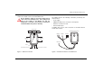
Installation 3.2 Installation procedures • It is recommended that the Mariner X2 is installed in a 'below decks' environment. Before beginning installation of your Mariner X2, please ensure you have the necessary additional items as detailed in section 3.1. It is strongly recommended that you read all of the instructions in this manual prior to installation. • It is acceptable to mount the Mariner X2 either vertically or horizontally.
Installation 137 mm 185 mm 84 mm 215 mm 45 mm 150 mm Figure 5 Mariner X2 dimensions Figure 6 Mariner X2 mounting Page 10
Installation Step 2 - Installing the GPS antenna For mounting of the GPS antenna provided with your Mariner X2 you will require a one inch 14 TPI thread pole. You should ensure the GPS antenna has a good clear view of the entire sky. It is not recommended that the GPS antenna is mounted up a mast where the the motion of the vessel will cause the antenna to swing and potentially reduce the accuracy of the GPS position. Do not mount your antenna in the direct path of a radar transmitter.
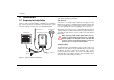
Installation Step 3 - Connecting the VHF antenna Step 4 - Connecting an external switch Route the cable from the VHF antenna to the Mariner X2 and connect to the VHF connector on the Mariner X2 as shown in Figure 9. If you require a remote external switch to activate the silent mode feature, it is possible to connect a toggle switch to the Mariner X2 and configure the switch function accordingly. A standard marine band VHF antenna or AIS antenna should be used with the Mariner X2.
Installation Step 5 - Connecting to a chart plotter The NMEA0183 data port provides the connection to your chart plotter and consists of four wires colour coded as shown in the table below and in Figure 11. Connect the wires to the appropriate connections on your chart plotter. Please refer to your chart plotter manual for more information.
Installation Step 6 - Connecting to a power supply The Mariner X2 requires a 12V power supply typically provided by the vessel's battery. ! Do not use a 24V power supply with the Mariner X2. Should a 24V supply be connected to the Mariner X2, an internal protection system will be invoked and the Mariner X2 will not operate as normal. However, no permanent damage will be caused to the Mariner X2. The Mariner X2 will operate as normal once connected to a 12V power supply.
Configuring your Mariner X2 4 Configuring your Mariner X2 Indicator lights Blue Red Amber Green 4.1 Switching on your Mariner X2 for the first time A few seconds after applying power to the Mariner X2 for the first time all four indicators (green, amber, red and blue) will blink twice. The indicator sequence following this will depend on whether your transceiver is pre-configured. Transceiver is pre-configured: The amber indicator will illuminate until the transceiver has transmitted an AIS message.
Configuring your Mariner X2 4.2 Introduction to the proAIS software Included in the CD supplied with your product is a configuration software tool called 'proAIS'. ! proAIS is only compatible with Windows based operating systems and is not compatible with Apple MAC operating systems. proAIS is a software tool which provides the facility to configure, monitor and diagnose issues with your Mariner X2. Section 4.3 provides instructions on how to install the proAIS software.
Configuring your Mariner X2 4.4 Configuration using proAIS ! ! Please ensure that you enter all static data accurately. Failure to do so could result in other vessels failing to identify your vessel correctly. The vessel MMSI can only be programmed once using proAIS, please take care to programme your MMSI correctly. If you need to change the MMSI for any reason, please contact your dealer who will arrange to have the MMSI reset.
Configuring your Mariner X2 7. Set the baud rates to the required level for each of the serial ports. • Set the RS232 baud rate to the required level. The default is 38,400. This is the baud rate used when communicating with a PC via the RS232 connection. • Set the NMEA output (transmit) baud rate to the required level. The default is 38,400. This is the baud rate used when transmitting data to a chart plotter via its NMEA0183 input. • Set the NMEA input (receive) baud rate to the required level.
Operation 5 Operation 5.1 Using the Mariner X2 Once the unit has been configured it is ready for use. Providing other vessels with Mariner X2s installed are within radio range of your vessel you should see their details appear on your chart plotter or PC. These vessels will also be able to see your vessel on their chart plotter or PC. It may take up to six minutes for your full vessel details to be visible to others.
Operation 5.3 Using proAIS with your Mariner X2 proAIS GPS status page The proAIS tool has a range of features to help monitor the performance of your Mariner X2. To use the full range of features your Mariner X2 must be installed as described in section 3 and connected to a PC running the proAIS application. The 'GPS status' page shows the signal strength of each satellite being received and the dynamic data of the vessel.
Operation proAIS Diagnostics page proAIS Other vessels page The 'Diagnostics' page provides a range of information about the Mariner X2's status. Referring to the information in this page may be useful if you are attempting to diagnose a potential issue with the Mariner X2's installation or operation. The 'Other vessels' page provides a list of all vessels from which AIS messages are being received.
Operation proAIS Messages page proAIS Serial data page The 'Messages' page provides a list of all text messages received from other vessels. These are most likely to be safety related messages which are requests for assistance from other vessels. The 'Serial data' page provides a view of all incoming and outgoing AIS messages. The messages are encoded in a special format and it is not necessary to understand the meaning of the messages to use the equipment.
Operation 5.4 Indicator functions The Mariner X2 includes four coloured indicators as shown in Figure 20. The state of the indicators provides information regarding the status of the Mariner X2. Indicator lights Blue Red Amber Green Figure 20 Indicator location on the Mariner X2 unit The meaning of typical indicator configurations is shown in the table below and Figure 20 shows the orientation of the Mariner X2.
Troubleshooting 6 Troubleshooting Issue Possible cause and remedy No data is being received by the chart plotter • • • No indicators are illuminated • • The Red 'error' indicator is illuminated • • • • • Check that the power supply is connected correctly. Check that the power supply is a 12V supply. Check that the connections to the chart plotter are correct. Check that the power supply is connected correctly. Check that the power supply is a 12V supply.
Specifications 7 Specifications Parameter Value Dimensions 215 x 150 x 45 mm (L x W x H) Weight 685g (Mariner X2 unit only) Power DC (9.6V - 15.6V) Average power consumption 4W Channel Bandwidth 25kHz Channel Step 25kHz Modulation Modes 25kHz GMSK (AIS, TX and RX) 25kHz AFSK (DSC, RX only) Bit rate 1200 b/s ± 30 ppm (FSK) RX Sensitivity Peak current rating 2A Connectors Adjacent channel 70dB IMD 65dB RS232 38.4kBaud bi-directional RS422 NMEA 38.
Warranty Information 8 Warranty Information b. Abuse, misuse, or any use of the Equipment in violation of the instructions set forth in the Manual; Limited Warranty c. Shipping, alterations, or incorrect and/or unauthorized service; This Limited Warranty (the “Warranty”) covers Mariner X2 Class B AIS product & accessories (the “Equipment”) sold by ComNav Marine Ltd. (“ComNav”). d.
Warranty Information antee that the Equipment will perform in accordance with the requirements of such usage; 3. ComNav reserves the right to modify the Equipment without any obligation to notify, supply or install any improvements or alterations to existing Equipment.
Warranty Information a. contact ComNav, by phoning 604-207-1600, to discuss the nature of the problem and to obtain return shipping instructions for the defective Equipment; and, 3. Warranty service shall be performed only by ComNav. Any attempts to remedy the defect by anyone else shall render the warranties set forth in this Warranty null and void. CHOICE OF LAW AND JURISDICTION b.
WARNING The Equipment is an aid to navigation only. It is not intended or designed to replace the person on watch. A qualified person should always be in a position to monitor the vessel’s heading, and to watch for navigational hazards, and should be prepared to revert to manual steering immediately if an undesired change of heading occurs, if the heading is not maintained within reasonable limits, or when navigating in a hazardous situation.
ComNav Marine Unit 15 - 13511 Crestwood Place Richmond, BC Canada, V6V 2G1 www.comnav.