
Operating instructions


R.5-MAX, R2-MAX Page 9 Installation and Operation Manual
STANDARD WIRING (R.5-MAX)
Connect as shown in Figure 6.
Figure 6. Standard wiring
(–) ( Black)
(+) ( White)
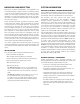
BIAMP WIRING
All R2-MAX are biamp models and have color coded gland
nuts (and a label on the enclosure - see Figure 7 below)
that will indicate what input the cable is designated for.
The cables are 2-conductor standard weather-resistant
cables 12' (3.6m) in length.
WIRING AND ELECTRICAL SAFETY
All standard R-MAX loudspeakers come with attached
SJOW rated input cables, 12' (3.6m) in length. The cable
enters the enclosure through a waterproof gland nut. The
other end of the cable is un-terminated. Beyond this length,
line-loss calculations should be performed when selecting
additional wiring to prevent losses in output due to voltage
drops resulting from increased impedance. Please contact
Community’s TAG Team (Technical Applications Group) for
additional assistance (email: tagteam@communitypro.com,
phone: (610) 876-3400, or toll-free (800) 523-4934 in the
US and Canada).
q Wire the loudspeaker. A typical installation method is
to bring the cable into a waterproof junction box (J-box)
equipped with a waterproof gland nut. Connections within
the J-box may be made with barrel-type crimp connectors,
wire nuts, solder and heat-shrink, or terminal strips.
Terminate per your local electrical code.
We recommend using barrel-type crimp connectors
that are crimped with a forged crimp tool (such as
Klein 1005) or a ratcheting tool (such as Klein T1720), as
this method, when properly executed, results in a gas-
tight connection that is quick and easy to accomplish.
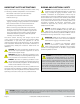
IMPORTANT: All electrical installation connections
for loudspeaker lines are subject to all applicable
governmental building and fire codes. The selection
of appropriate electrical hardware to interface with the
R SERIES loudspeaker lies solely with the installation
professional. Community recommends that an
appropriately licensed engineer, electrician, or other
qualified professional identify and select the appropriate
conduit, fittings, wire, etc. for the installation.
DANGER: The output power capabilities of audio
amplifiers present a danger to installers. To
minimize the risk of electric shock from
loudspeaker connecting cables, confirm that the power
amplifiers are turned “o" before connecting loudspeaker
cable(s) to the loudspeaker or amplifier. Always follow
local electrical codes and proper electrical safety
procedures.
WARNING: After wiring the amplifier(s) to the
loudspeaker(s), first power-up all devices that are
upstream of the amplifier, such as mixers,
equalizers, compressor/limiters, etc., before powering-up
the amplifier. This is to avoid passing any clicks or pops that
may originate in the upstream devices to the loudspeakers.
The amplifier should initially be powered-up with its gain
controls turned all the way down. After making sure that a
continuous signal is present, such as a CD playing, slowly
raise the level of the gain controls to establish that the
wiring has been installed correctly. Only then should the
loudspeaker be operated at normal output levels.
Figure 7. Labeled cables - R2-MAX
FINAL ASSEMBLY AND TESTING
q All holes should be filled with the provided hardware or
other suitable replacement in order to maintain weather-
resistance.
q Attach a safety cable to an attachment point on each
loudspeaker. The safety cable and hardware are not
included. Please consult a structural engineer for the
appropriate cable for the load and application. The safety
cable attachment points should not be located on opposite
sides of the cabinet in such a manner that they present a
significant force that pulls the insert points away from each
other. The safety cable must be secured to a suitable load-
bearing point separate from the loudspeaker mounting
point, with as little slack as possible, so as not to develop
undue kinetic force if the R SERIES mounting were to fail.
q Power and test the system.
MF/HF connection
(white gland nut)
LF connection
(black gland nut)