
Operating instructions


Community CLOUD12 – Operation Manual - Page 15
WIRING AND INSTALLATION
This manual will serve to assist in wiring and physically mounting CLOUD1266, CLOUD1266T, CLOUD1299,
CLOUD1299T, CLOUD12SUB and CLOUD12SUB-T loudspeakers. The directions include assistance to those
installers using a complete Community package of loudspeakers and accessories, including the C12BB3
backbox, C12SQGRL square grille and appropriate tile rails. If accessory products from a different
manufacturer are used, please refer to the installation manuals supplied with those products.
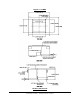
For protection against electrical shock and to meet the requirements of the UL2043
standard, the speaker assembly must be installed in a Listed Community Model C12BB3
Back Box or similar UL1480/UL2043 listed enclosure. Minimum dimensions for the
enclosure must be 23” wide x 20” deep by 12” tall with a minimum wall thickness of
1.2mm.
Installing Backbox Fittings for Conduit and Strain Relief
Required tools:
One hammer and knockout punch tool
One step-bit for adjusting knockout diameter (optional)
Safety glasses, gloves and other personal safety gear are recommended as this process involves
striking metal parts and chipping away debris around the knockouts.
NOTE: All electrical installation connections for speaker lines are subject to local, state, and federal
building & fire codes. The selection of appropriate electrical hardware to interface with the C12BB3
lies solely with the installation professional. Community recommends that an appropriately licensed
engineer, electrician, or other professional identify and select the appropriate conduit, fittings, wire,
etc. for the installation.
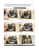
Instructions for installing backbox fittings for conduit and strain relief:
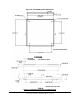
1. The C12BB3 comes equipped with knockout fittings on each side panel measuring:
a. 21/32” (17mm) to accommodate 3/4” fittings
b. 15/16” (24mm) to accommodate 1” fittings
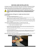
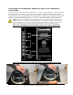
2. The knockouts are removed with a hammer and punch using the same techniques for removing
knockouts in other types of electrical boxes. A step-bit can be used to modify the diameter of the
knockout to accommodate larger conduit sizes.
3. Insert appropriate fittings and tighten sufficiently for wire path concealment and strain relief, in
accordance with applicable codes.
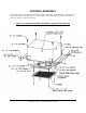
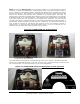
4. The acoustical damping batting material on the interior of the C12BB3 backbox should not cover the
inside surface of knockouts. If the batting covers the knockouts, peel back about four inches to
expose the knockouts. Trim off any excess batting that has been peeled back so that it will not
interfere with the loudspeaker’s function.
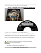
White mastic acoustical material on the C12BB3 (looks like white plaster) can be chipped away as needed to
allow electrical fittings to seat securely on the metal surface surrounding the knockout.
Figure 13: Knocking out the knockout with a hammer and punch