CLOUD12 12-Inch Ceiling Loudspeakers Models: CLOUD1299 / CLOUD1299T CLOUD1266 / CLOUD1266T CLOUD12SUB / CLOUD12SUB-T Installation and Operation Manual
EC STATEMENT OF CONFORMITY This document confirms that the range of products of Community Professional Loudspeakers bearing the CE label meet all of the requirements in the EMC directive 89/336/EEC laid down by the Member States Council for adjustment of legal requirements. Furthermore, the products comply with the rules and regulations referring to the electromagnetic compatibility of devices from 30-August-1995.
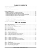
TABLE OF CONTENTS IMPORTANT SAFETY INFORMATION .......................................................................................... 4 UNPACKING AND INSPECTION ................................................................................................. 5 CLOUD12 OVERVIEW.............................................................................................................. 6 Table 1: CLOUD12 models and accessories ............................................................................
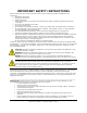
IMPORTANT SAFETY INSTRUCTIONS Always follow these basic safety precautions when using or installing CLOUD12 loudspeakers and accessories: Read these instructions. Keep these instructions. Heed all warnings. Follow all instructions, particularly those pertaining to rigging, mounting, hanging and electrical connections. Do not use this apparatus near water. Clean only with dry cloth Do not block any ventilation openings. Install in accordance with the manufacturer’s instruction.
Utilisez seulement les accessoires qui sont spécifiés et approuvés par le fabricant. Débranchez cet appareil pendant les orages de foudre ou si inutilisé pendant de longues périodes. Référez tout entretient au personnel qualifié de service.
CLOUD12 OVERVIEW Thank you for purchasing your new Community CLOUD12 Series High Output Ceiling Loudspeakers. The CLOUD12 and CLOUD12SUB ceiling loudspeakers are extremely high output devices, intended to meet the needs of the professional sound contractor for a variety of professional sound installation applications.
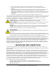
C12BB3 3.0 cubic foot metal backbox for CLOUD12 ceiling loudspeakers C12SQGRL Square white grille for CLOUD12 ceiling loudspeakers RAIL24-PR Pair of 23.75-inch channel rails for CLOUD12 ceiling loudspeakers RAIL30-PR Pair of 30-inch channel rails for CLOUD12 ceiling loudspeakers RAIL48-PR Pair of 47.
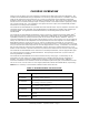
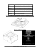
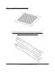
Figure 3: C12SQGRL square white grille Figure 4: Channel rails available in lengths of 23.75 inches, 30 inches and 47.
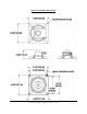
Figure 5: CLOUD12 dimensions Community CLOUD12 – Operation Manual - Page 9
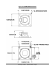
Figure 6: CLOUD12SUB dimensions Community CLOUD12 – Operation Manual - Page 10
Figure 7: C12BB3 backbox dimensions Community CLOUD12 – Operation Manual - Page 11
Figure 8: C12SQGRL grille dimensions Figure 9: RAIL24-PR channel rail dimensions Community CLOUD12 – Operation Manual - Page 12
Figure 10: RAIL30-PR channel rail dimensions Figure 11: RAIL48-PR channel rail dimensions Community CLOUD12 – Operation Manual - Page 13
CLOUD12 ASSEMBLY The assembly diagram below illustrates how the CLOUD12 loudspeaker, C12BB3 backbox, C12SQGRL grille and channel rails are assembled together. Please note that the C12BB3 ships as a backbox only, and all other parts shown are optional accessories.
WIRING AND INSTALLATION This manual will serve to assist in wiring and physically mounting CLOUD1266, CLOUD1266T, CLOUD1299, CLOUD1299T, CLOUD12SUB and CLOUD12SUB-T loudspeakers. The directions include assistance to those installers using a complete Community package of loudspeakers and accessories, including the C12BB3 backbox, C12SQGRL square grille and appropriate tile rails.
Connecting Strain Relief to Cable and Loudspeaker Assembly Pass the loudspeaker cable through the appropriate knockout opening in the backbox and secure the cable with a standard electrical tie-wrap (not provided) to provide strain relief (see figures below).
Connecting the Loudspeaker Cable for 8 Ohm (Low Impedance) Connections Connect the common side of the speaker cable to the " - " terminal on the input block. Connect the positive side of the speaker cable to the " + " terminal on the input block. 14 AWG twisted pair speaker cable is recommended for most 8 ohm applications when using spade or ring terminals. The speaker input block will accept up to 10 AWG cable directly without spade terminals.
Connecting the Loudspeaker Cable for 70V/100V Connections Connect the common side of the speaker cable to the “common” terminal on the input block. Connect the positive side of the speaker cable to the appropriate 70V/100V wattage tap based on the requirements of the project. For multiple 70V/100V speakers, attach the subsequent speakers by parallel connecting them to the “common” and appropriate autoformer input terminals of the previous speaker.
NOTE: The electrical damping factor of the subwoofer amplifier is a critical factor when selecting equipment to support the CLOUD12SUB. Damping factor refers to the power amplifier’s ability to stop (or “dampen”) a reproduced frequency. The higher the damping factor, the better the amplifier will control the LF driver. Bass frequencies are more difficult to control than higher frequencies, and therefore the damping factor becomes more important to the overall system.
The CLOUD12SUB-T ceiling subwoofer is shipped with a 5-conductor cable for connection to the appropriate autoformer input position. See the figures below for input terminal designation. Figure 20: CLOUD12SUB-T wiring and input panel (70V/100V operation) Attaching Channel Rail Kits to the C12BB3 Backbox Community offers rail kits in three popular lengths: 24 inches, 30 inches and 48 inches.
Figure 21: Channel rail kit with tools and accessories Instructions for attaching the channel rails to the backbox: 1. Unpack a. b. c. d. e. f. the RAIL24-PR, RAIL30-PR, or RAIL48-PR kit and find the following contents: Two mounting rails (4) 1/4-20 x 1” Hex Head Screws (4) 1/4” Hex Nuts (8) 1/4” Flat Washers (4) 1/4” Lock Washers Liability Waiver Card 2. Set rail along one side of the C12BB3 backbox so that the leg of the rail aligns with the slotted holes against the slotted tabs. 3.
Figure 22: Tightening the rail kit to the backbox Suspending the C12BB3 Backbox The C12BB3 backbox will generally be installed in tile-based ceiling systems, but can also be installed in open space. Use eyebolt kits (part number 1/4EYBLTKIT) to fasten conventional rigging hardware to the C12BB3. NOTE: There are several 1/4-20 suspension points located in the back panel of the C12BB3. These can be used as alternate support and rigging points for open ceiling plan installation.
Figure 23: “Snugging” the ¼-inch eyebolts Eyebolt Suspension: The eyebolts must be screwed in so that the shoulder firmly contacts the surface of the enclosure. In all cases the direction of pull on the eyebolt and mounting point should not exceed a maximum of 45º from the vertical axis of the mounting point hole. Multiple cables that can independently support the loudspeaker must also be used. See the following figure.
Attaching the CLOUD12 Loudspeaker to the C12BB3 Backbox NOTE: The CLOUD12 loudspeaker weighs approximately 20 lbs and the C12BB3 backbox weighs at least 40 lbs. Both are awkward and difficult to handle. Lift the CLOUD12 by the speaker basket or main support backing only; do not use the terminal strip or the autoformer (70V/100V versions only) as a lift point. It is highly recommended that two people work as a team to install the C12BB3 backbox into the ceiling and the CLOUD12 assembly into the backbox.
5. Set the CLOUD12 into the square hole in the C12BB3. Handle the speaker assembly by its metal frame or baffle plate. Be careful to not handle the weight of the assembly by the electronic parts or the speaker’s paper cone. It will likely require the assistance of a second worker to hold the CLOUD12 speaker assembly. Alternately, a fixture might be devised to safely support the speaker frame while fastening it into the C12BB3. 6.
Attaching the C12SQGRL Grille to the CLOUD12/C12BB3 Assembly Required tools: One #2 Philips Screwdriver Superlative vision and a flashlight to see the tiny black holes behind the grille when inserting the screws Safety glasses are highly recommended Instructions for attaching the grille to the loudspeaker and backbox assembly: 1. Unpack C12SQGRL and inspect contents to find the following: (1) C12SQGRL white grille (4) 8-32 x 1-1/2” Philips truss head screws 2. The C12SQGRL is provided in white.
WARRANTY INFORMATION AND SERVICE Transferable Warranty "(Limited)” Valid in the USA Only Community CLOUD12 ceiling loudspeakers are warranted in the USA to be free from manufacturing defects in materials and workmanship for a period of five years, as determined by one of the following two methods, whichever is longer: Starting from the date of retail purchase, as noted on the sales receipt from an authorized Community dealer, OR Starting from the date of manufacture, determined by the serial number, if the
Consequential and Incidental Damages: Community shall not be liable for any consequential or incidental damages including, without limitation, injury to persons, property, or loss of use. Some states do not allow the exclusion or limitations of consequential or incidental damages, so the above limitations and exclusions may not apply. This Community warranty is not extended by the length of time which an owner is deprived of the use of the product.