
User Manual

Cell Extender Electrical & Mechanical Specification
Communication Components Inc.
PCS GSM Multi-Channel Cell Extender
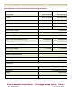
Uplink Downlink
A & D Blocks 1850-1870 MHz 1930-1950 MHz
B Block 1870-1885 MHz 1950-1965 MHz
C Block 1895-1910 MHz 1975-1990 MHz
System Gain 10 dB 10 dB
System Noise Figure: 2.5 dB Max.
System Group Delay: 180 nanoseconds Max
Pass-band Ripple: 0.5 dB Max.
Output Third Order Intercept Point: +31 dBm Min. +59 dBm Min
1 dB Compression Point: +22 dBm Min. +51 dBm Min
Input /Output VSWR: 1.5:1 Max. 1.5:1 Max.
Up-Link-Down-Link Isolation 80 dB
Number of Inputs/Outputs: 1/1
Power Supply Voltage: 110/220 VAC
Current Consumption: 1.5/0.75 AMPS
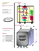
Dimensions
Enclosure NEMA 4x Weather Proof
Connectors 7/16 DIN Type Female
Weight 20 Lbs. Max.
Mounting Pole and/or Wall Mountable
E & F Blocks 1885-1895 MHz 1965-1975 MHz
Maximum Usable GSM/EDGE Power: N/A 20 Watts Composite
Communication Components Inc.
Tel: 201-342-3338 Fax: 201-342-3339