THEORY OF OPERATION The BDA-1819-60 is a bi-directional amplifier. It is designed to exchange radio communications in buildings, basements, tunnels and other RF shielded environments. The BDA improves the sensitivity of base stations in indoor locations where there is a significant amount of cable loss in RF distribution systems. BDA-1819-60 operates in designated PCS bands. It contains two amplifiers providing amplification of RF signals in Up-link and Down-link frequency bands.
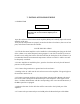
TECHNICAL DESCRIPTION The BDA-1819-60 bi-directional amplifier provides signal amplification in two separated frequency bands in both directions between two coaxial connector terminals. It is achieved by utilization of two frequency selective duplexers, which direct signals at two frequency bands present at the common port in two outputs. These duplexers provide sufficiently high isolation between two paths to prevent self-oscillation of the system. Detailed blockdiagram is shown in Figure 1.
Line Bi -Directional Amplifier BLOCK DIAGRAM B IA S TEE R x/Tx D U PLEXE R Rx B PF Tx B PF AM P AM P AC Power Supply Variable A ttenuator Variable A ttenuator Variable attenuators and AGC are optional AM P AM P Tx B PF Rx B PF R x/Tx D U PLEXE R B IA S TEE Figure 1 Bias Tee’s are optional
INSTALLATION MANUAL for BI-DIRECTIONAL AMPLIFIERS Communication Components Inc. 299 Forest Ave, Paramus, N.J.
TABLE OF CONTENTS 1. Theory of Operation 2. Technical Description 3.
1. THEORY OF OPERATION The BDA-1819-60 is a bi-directional amplifier. It. is designed to exchange radio communications in buildings, basements, tunnels and other RF shielded environments. The BDA improves the sensitivity of base stations in indoor locations where there is a significant amount of cable loss in RF distribution systems. It contains two amplifiers providing amplification of RF signals in Up-link and Down-link frequency bands.
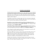
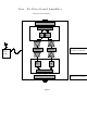
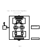
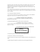
2. TECHNICAL DESCRIPTION The BDA-1819-60 bi-directional amplifier provides signal amplification in two separate frequency bands in both directions between two coaxial connector terminals. It is achieved by utilization of two frequency selective duplexers, which direct signals at two frequency bands present at the common port in two outputs. These duplexers provide sufficiently high isolation between two paths to prevent self-oscillation of the system. Detailed blockdiagram is shown in Figure 1.
Line B i -D irectional A m plifier B L O C K D IA G RA M B IA S T E E R x/T x D U P LE XE R Rx B PF Tx BPF AM P AC Power Supply AM P V ariab le A tten uator V ariab le A tten uator Variable attenuators and AGC are optional AM P AM P Tx BPF Rx B PF R x/T x D U P LE XE R B IA S T E E Figure 1 Bias Tee’s are optional
3. INSTALLATION PROCEDURE 3.1 INSPECTION CAUTION Use caution working with the bi-directional amplifier. Disconnect the 115 VAC from the amplifier prior to inspection. Open the enclosure of the bi-directional amplifier (BDA) and carefully inspect the inside assembly of the unit. Verify that all components are properly secured to the base of enclosure, there are no lose parts, and all interconnections are reliable. 3.2 SITE INSTALLATION 3.2.
Connect the “donor” side cable to the Up-link port of the BDA. Observe the level of the amplified signals on the spectrum analyzer. Adjust the gain (if the BDA option is so equipped) or external (internal, if so equipped) attenuator value to limit the power of the signals to +28 dBm. 3.2.8 Repeat the same measurements connecting the spectrum analyzer to the Up-link port and cable to the Down-link port. Adjust the level of amplified signals at the Up-link port to +28 dBm. 3.2.
3.6.0 INFORMATION TO USER Any changes or modifications to this product as well as usage outside of specified electrical parameters, which are not expressly approved by manufacturer, could void the user’s authority to operate the equipment.
Drawing for FCC ID Label 3.0" Communication Componets, Inc. Model No: BDA-1819-60 FCC ID: NT3BDA-1819-60 1.