
User manual


ECE 477 Final Report Spring 2004
Because we are implementing a memory map model, our code and stack will be
relatively sleek, but we will need a chunk of space to store it. However, external memory is not
needed because of the built-in 8k memory of the LCD module. The memory map will be
structured like the screen itself… each “line” of memory will be a line of text on the menu. The
first line is 0x00-0x1F (0-31); the second line is 0x20-0x3F and so forth. Each screen is one
“page” of 8 lines. Each screen can be accessed as a simple mathematical operation based on the
location passed as the beginning of the first line. A corresponding (and smaller) function map
will store whether or not the line is simply text or a menu, and if a menu, the memory location of
the submenu to display should the current item be displayed.
Startup Code
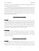
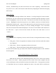
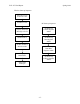
The base and mobile units will each have different but similar start-up sequences. Flow
charts of start-up procedures are included in the appendix.
The LCD module has rather specific startup instructions. The sample start-up sequence
for the LCD is 32 steps long, so for details please refer to the documentation listed in the
References section. Only a general flow chart will be provided to start-up the LCD, separate
from the other start-up flow charts. Several details need to be initialized on the driver chip, such
as the dimensions of the LCD screen and the number of “layers” to use, such as text layer and
graphics layer. The module is 128x128 pixels, and will only use the text layer.
The RF startup sequence will be the same on both the base and mobile units. Where the
LCD needs 32 steps, the RF needs 4; and order is not so important so long as they are done
before data needs to be sent. A flow chart of this is also included in the appendix.
Organization of Embedded Application Code
The embedded application code will be written in embedded C. Aside from the start-up
sequence, the program will tell the unit to sleep and wait for changes in input on the interrupt
pins to run service routines (according to lecture, the “interrupt-driven” solution). The wireless
device will wake up on a button press, calculate the next memory address, navigate the menu,
send an order if needed, and go back to sleep to save power. It will also wait for an interrupt
from the RF chip, at which point it will receive a new menu from the base computer and store it
-33-