
Instructions
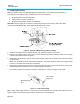
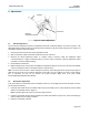
Table Of Contents

www.commscope.com
408-8738
Instruction Sheet
Page 5 of 6
6. Adjustments
Figure 5. Ratchet Adjustment
6.1 Ratchet Adjustment
The tool ratchet mechanism features an adjustment wheel with numbered settings, as shown in Figure 5. The
adjustment wheel controls the amount of handle pressure exerted on the jaws during crimping. If the crimp is not
acceptable, adjust the ratchet as follows:
1. Remove the lockscrew from the ratchet adjustment wheel.
2. With a screwdriver, adjust the ratchet wheel from the front of the tool.
3. Observe the ratchet adjustment wheel. If a tighter crimp is required, rotate the adjustment wheel
counterclockwise to a higher-numbered setting. If a looser crimp is required, rotate the adjustment wheel
clockwise to a lower-numbered setting.
4. Re-assemble the lockscrew.
5. Make a sample crimp. If the crimp is acceptable, the adjustment setting is correct. If the crimp is unacceptable,
continue to adjust the ratchet, and again measure a sample crimp.
Note: The tool is set at the No. 7 ratchet setting at the factory. This setting assures the proper crimp height for
solid wire and accounts for the maximum tolerance in the tooling. You can readjust your tool to a lower setting,
(No. 4, minimum), as long as you achieve the proper insertion depth, 6.02 ±0.13 [.237 ±.005).
See the applicable application specification.
6.2 Wire Stuffer Adjustment
If the wire stuffer is not assembled onto the insulation stuffer or if correct alignment of these two parts is unsure,
proceed with the following:
1. Install the wire stuffer onto the insulation stuffer using the 4-40 UNC .621 in. socket head cap screw included
with the die assembly. Refer to Figure 2.
Note: DO NOT tighten the screw. If the screw is tight, loosen it.
2. Close the tool handle until the ratchet releases, then allow the handles to open FULLY. Insert a modular plug
(without cable) into the crimping chamber.
3. Close the tool handle, and hold.
Screwdriver
Ratchet
adjustment wheel
Lockscrew