
User's Manual


Table Of Contents
IP-RN 8000 I&C Guide 113
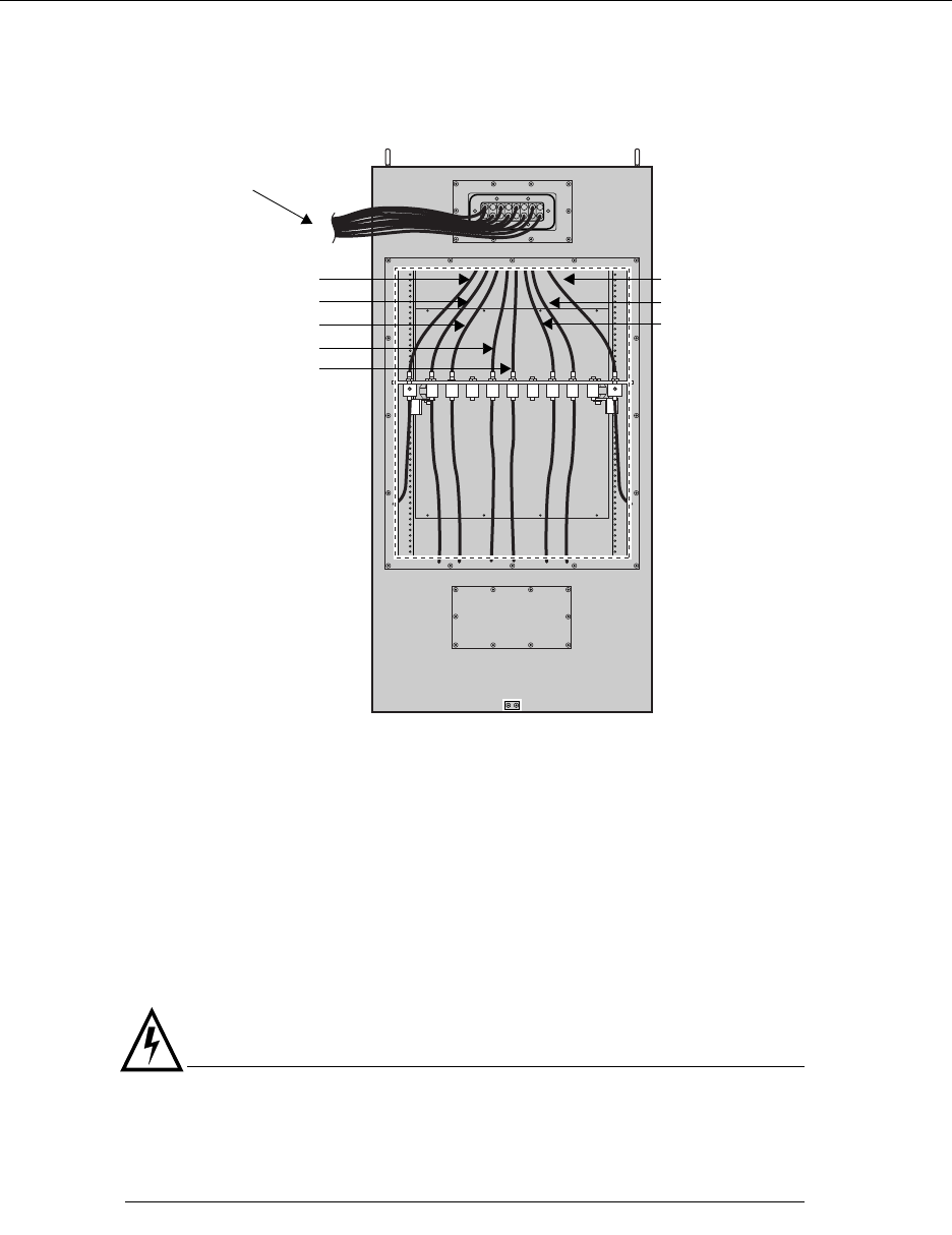
4. After all internal antenna cables are connected to the correct surge suppressors, the cabinet appears as
shown in the following figure.
5. Retrieve the 16 tamper-proof screws and rubber washers that you set aside when removing the panel.
6. Ensure the access panel is undamaged:
• Examine the inside edge of the access panel. The gasket on the inside edge must be intact to ensure
a proper seal.
• A spacing washer must be embedded in the gasket for each screw.
7. Position the surge protection access panel and screw in the top middle screw by hand.
Be sure to thread the rubber sealing washer on the screw shank before inserting it in the access panel
screw hole.
WARNING
Screws should be started by hand. It is possible to damage the thread in the cabinet if you use
hand tool or a power tool. Damaged threads must be repaired or the cabinet will be improperly
sealed and the IP-RN 8000 can be damaged. Use a thread tapping set to fixed damaged
threads.
8. Start the remaining 15 screws (with washers) by hand. Install them loosely before tightening any one of
them.
RF and GPS antennas
Secondary GPS
leading to external
surge suppression equipment
Gamma sector RX1
Gamma sector TX/RX0
Beta sector RX1
Beta sector TX/RX0
Primary GPS
Alpha sector TX/RX0
Alpha sector RX1
Rear view - 6 RF/2 GPS cable configuration