
User's Manual
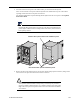
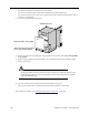


Table Of Contents
IP-RN 8000 I&C Guide 111
1. Look at the surge suppression bar in the cabinet and compare it with that shown in the following figure.
Use the label on each cable to plan which cables dangling from the inside of the Rox System cabinet
seal will connect to which connectors on the surge protection bar.
It is essential that the proper cables are connected to the proper surge suppressors. Each cable on the
Rox System cabinet seal is labeled on both ends, both the end that dangles inside the cabinet and the end
that is outside the cabinet. See Understanding the antenna installation process
on page 98.
WARNING
If you connect cables to the wrong surge suppressors, damage to equipment may occur and the
equipment may not operate correctly.
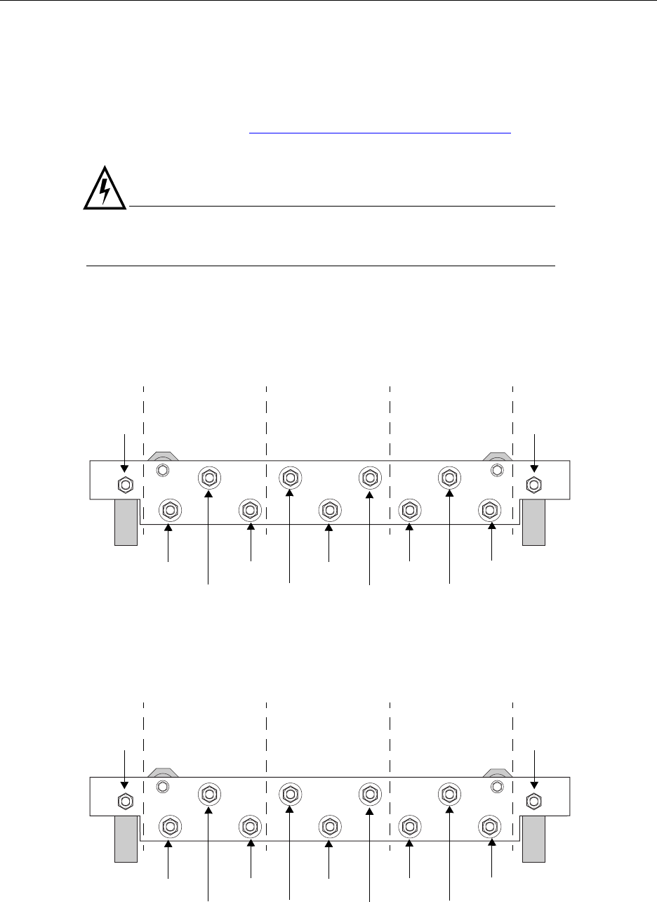
If your deployment uses two antenna cables per sector, connect the cables to the connectors as follows:
If your deployment uses three antenna cables per sector, connect the cables to the connectors as follows:
Surge suppression bar — top view from the rear
Gamma (χ)
sector
Beta (β)
sector
Alpha (α)
sector
RX1
Unused
TX/RX0 RX1 Unused
TX/RX0
RX1
Unused
TX/RX0
Primary GPSSecondary GPS
Cable connections with two RF cables per sector
Gamma (χ)
sector
Beta (β)
sector
Alpha (α)
sector
RX1
RX0
TX RX1 RX0
TX
RX1
RX0
TX
Primary GPSSecondary GPS
Surge suppression bar — top view from the rear
Cable connections with three RF cables per sector