
User Guide


4.2 Digital Inputs and Outputs
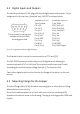
The robot base shows a D-Sub plug with several digital inputs and outputs. The pin
assignment for the versions „Standard“ and „24V DIO“ are shown below.
D-Sub Female: View from the
outside on the pins. Male
according mirrored.
Standard: 5V DIO
Type: Female
Pin 1: 5V
Pin 2: In 3
Pin 3: In 1
Pin 4: Out 3
Pin 5: Out 1
Pin 6: GND
Pin 7: In 4
Pin 8: In 2
Pin 9: Out4
Extension: 24V DIO
Type: Male
Pin 1: Out1 24V
Pin 2: Out2 24V
Pin 3: Out3 24V
Pin 4: In1
Pin 5: In2
Pin 6: In3
Pin 7: In4
Pin 8: GND
Pin 9: 24V Supply
Pic. 4: Pin assignment at the base digital IO plug
The Standard robot is set up for communication on TTL level (5V).
The 24V-DIO-Extension provides relays and 24V digital inputs, allowing to
communicate with a PLC on 24V level.The outputs are able to provide 1A each,
forwarding the external supply voltage from pin 9. The inputs are 24V.
Two further digital outputs can be found on the flange of the robot, see the next
section.
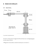
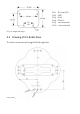
4.3 Mounting Flange for the Gripper
The robot flange offers 10 M3 threads to connect gripper or other devices. A plug
allows electrical connectivity.
Six of the threads are placed on a 15 mm reference circle; the remaining 4 M3
threads are located as shown in the drawing. The plug is a Harting product SEK male
6 poles: