Bedienungsanleitung Mover4
User Guide Mover6 Version 2014/07 (SW V902-06-016, HWE 2MV11 HWM V02 DOC V01) © Commonplace Robotics GmbH, 2011 - 2014 Commonplace Robotics GmbH Osterfeldstr. 1 D-49326 Melle Germany ++49 5429 / 374983-4 info@cpr-robots.com www.cpr-robots.com The CE sign confirms that this product meets the requirements of the directive 2004/108/EC (EMC) and 2002/95/EC (RohS). The according documentation is deposited at the manufacturer.
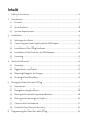
Inhalt 1. Safety Instructions............................................................................................................................. 6 2. Introduction ............................................................................................................................................7 3. 4. 5. 6. 2.1 Product ..............................................................................................................................................7 2.
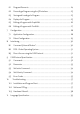
6.1 Program Elements ................................................................................................................... 24 6.2 Recording a Program using the 3D Interface .............................................................. 25 6.3 Saving and Loading of a Program ...................................................................................... 25 6.4 Replay of a Program ......................................................................................................
1. Safety Instructions • The Mover6 is designed to be used by adolescents and adults in edutainment and research areas. • The robot must not be used in industrial production facilities of in other continuous operation scenarios. • Do not operate the robot when it is unattended. • The gripping area exposes the risk of bruises to the fingers, especially when using the parallel gripper.
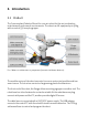
2. Introduction 2.1 Product The Commonplace Robotics Mover6 is a six axis robot for the use in education, entertainment and research environments. The robot can lift a payload up to 500 g with a reach of 550 mm plus gripper. Pic. 1: Robot arm and the necessary components (here with the Mover4 robot arm) The modular set up of the robot connects four servo motor joint modules and two smart servos. The structure consists of engineering plastic and aluminum.
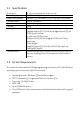
2.2 Specifications Nr of Joints Power Supply Power Consumption Communication Reach Payload Inputs / Outputs Communication 6 (4 servo joints and 2 smart servos) 12V DC at max 5 A Paused: 0,5 A / in motion: < 2.5 A. Fuse with 2.5 A in base CAN at 500 kBit/s 455 mm plus gripper 200 g At the base: 3 digital outputs (5V / 25 mA) and 4 digital Inputs (5V) via D-Sub 9 poles female. or, with 24V-DIO Extension: 3 relay out (24V/1A) and 4 digital in (24V) via D-Sub 9 poles male.
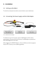
3. Installation 3.1 Setting up the Robot The robot has to be placed on a table or stand so that he cannot tumble down. 3.2 Connecting the Power Supply and the USB Adapter Pic. 2: Cable loom and USB adapter The cable loom connects the power supply, the USB adapter and the robot as depicted above. All connectors fit only one way. The USB adapter may be white or black, depending on the current type. When plugging in the USB2CAN adapter, a driver installation assistant may appear. Please refer to section 3.
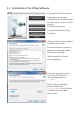
3.3 Installation of the CPRog Software Insert the CPRog CD into the drive. Depending on your systems configuration the CD menu will open automatically, or you have to start it manually: D:\.autorun\autorun.exe Choose the first button „CPRog Installation” Maybe you have to allow changes to be made on your system. After the installer has started you need to choose between English and German as language. Then you need to confirm the license agreement. In the next step you can choose where to install CPRog.
The installation normally takes only a few seconds. The installer checks, if DirectX 9.5 is installed. If not it will install theses libraries from the CD or via download. This will take some minutes. The installation of DirectX 9.5 is necessary even if e.g. DirectX 11 is already installed. When finishing the installation you can choose to directly start CPRog. Now you can start CPRog using the link on the desktop or via the start menu.
3.4 Installation of the Driver for the USB Adapter The robot is delivered with the PCAN USB driver from www.peak-system.com. To run the adapter the according driver has to be installed. This can be done from the CPRog installation CD (button “Install USB-CAN adapter”), or using the manufacturers installation CD. After starting the installation you need to • accept the license agreement and • set the installation folder.
3.5 Licensing The CPRog software needs a license key to start. This key is in most cases already integrated into the installation version of CPRog. Nothing has to be done. If it is not, e.g . because you have installed a demo version, please see the following information. The key, an XML file, has to be stored in the directory \CPRog\Data\License The CPRog installer copies the key Demo.xml to the directory. With this key CPRog starts in demo mode.
4. Robot Arm Mover6 4.1 Geometry Pic. 3: Mover6 simplified side view The picture shows the joints length of the Mover6 robot arm. Including the gripper the arm reaches 625 mm. CPRog offers functionalities to limit the workspace, see section 7.2.
4.2 Digital Inputs and Outputs The robot base shows a D-Sub plug with several digital inputs and outputs. The pin assignment for the versions „Standard“ and „24V DIO“ are shown below. D-Sub Female: View from the outside on the pins. Male according mirrored.
Pin1: Pin2 Pin3: Pin4: Pin5: Pin 6: Pic. 5: Drawing of the flange 4.4 Drawing of the Robot Base The robot can be mounted using the M4 through holes. Pic. 6: Drawing of the robot base plate 12V, max 0.
5. Moving the Robot Arm with CPRog 5.1 Introduction The CPRog programming environment allows to control and program the Mover robot. Both online and offline working is possible. Pic. 7: CPRog User Interface In the upper area the three ribbons “Scene”, “Motion” and “Programming” provide access to the main functionalities. On the left corner information on the robots current state are provided.
5.
The „Joint“ mode allows to turn the single robot axis from A1 to A4. In “Cartesian” mode the robot moves in straight lines following the x, y and z coordinate axis. The rotation is defined with the B commands. In „Cartesian Tool” mode the robot moves aligned to the current tool coordinate system. The override scales the motion speed between 0 and 100%. Pic. 9: Buttons to jog the robot in Cartesian mode. In joint mode the buttons change to the axis A1 to A4.
Reference: 1. Change motion mode 2. Change active robot 3. Open / close gripper 4. Record a motion point 5. Change button assignment: when pressed it is not +X, but +B Pic. 10: Assignment of keys for the joypad. Upper markings for Cartesian mode, lower for joint mode. 5.4 Moving the Robot using the Graphics An alternative to the joypad is to drag the robot in the graphical 3D environment. When selecting a joint of the robot with the left mouse button, the joint outlines blink red.
5.5 Connect with the Hardware The real robot can be controlled in the same way as the simulated one, only the hardware has to be connected before: connect, reset errors and enable motors. Prerequisites are that the robot is connected via the USB-CAN adapter and the robots supply is running (plugged in, switched on and emergency button released). Pic. 11: Buttons to connect to the hardware, reset the errors and enable the motors Step 1: Connect with the hardware.
5.6 Reset the Zero Points of the Joints The joint modules 1 to 4 keep track of their position using incremental encoder. The joint electronics stores these positions in their non volatile memory, so that the robot is aware of his current position after being switched on. Joints 5 and 6 provide absolute position encoder, there is no need to store the current position. It may happen that the stored values are not correct, then the joints need to be calibrated.
When the robot is in the correct position press “LogoCircle/Configuration/SetJointsToZero” in the upper left menu. Confirm the following dialog with „OK“. This function takes back the motor enabling, so the error reset and enable motor buttons have to be pressed. The precision of the calibration is vital for replaying old programs. If theses old programs (recorded before the calibration) show precise motions close to the environment they have to be replayed slowly the first time.
6. Programming the Robot Arm with CPRog 6.1 Program Elements A Mover6 robot program is build out of the following commands: Lin The robot moves on a straight line from the current position to the target position. The velocity is defined in mm/s. Joint Interpolates the axis from the current position to the target position in joint coordinates. Velocity is defined as percentage of the maximum joint rotational velocity.
6.2 Recording a Program using the 3D Interface Using the 3D screen a program can be recorded using the joypad or the buttons. Joypad: Every time the A button (or button 2) on the joypad is pressed a linear command to the current robot position is recorded. If necessary a command to open or close the gripper is added, together with a short break. A sound indicates that the point was recorded. Program Buttons: If there are still commands in the memory, they can be deleted using the Delete button.
6.5 Editing a Program with GraphEdit The button Programming/Editor opens a graphical program editor. This editor allows in a puzzle visualization to adapt and create programs. Pic. 13: Graphical program editor In the upper left area common elements are found, Undo/Redo and Load/Save. Two further buttons need explanation: • The dust bin deletes the selected puzzle piece • The light bulb updates the program on the current robot to the updated version. It also saves the program.
6.6 Editing a Program with TextEdit Using the button beneath GraphEdit opens the TextEdit Program editor. This editor is more usable for bigger programs and provides more information. Pic.
7. Configuration 7.1 Application Configuration The application configuration can be done by adapting the parameters in different XML files. 7.1.1 Startup Configuration The file c:\CPRog\CPRFrontend.xml allows to set the language and the start project. Possible choices are DE and EN. 7.1.
7.2 Robot Configuration For each robot in the CPRog simulation a XML config file exists, e.g. C:\CPRog\Data\Robots\CPRMover6\CPRMover6.xml Definition for the velocities in Jog mode: A virtual cell can be defined as a safety space the robot cannot leave in Cartesian mode: The cell walls are not active in joint mode.
8. Interfacing 8.1 Command „External Motion“ Using the „External Motion“ command is an easy way to integrate external control, e.g. a vision system. When the robot reaches this command in program replay he hands control over to the external program. He gets connected defined by IP address and port. The scale parameter adapts the velocity. The steps are: • When starting the robot program CPRog connects as client at the server at IP:Port.
The parameter Scale adapts the velocity. When the last answer from the server is older then 500 ms the robot does not move. A Java/Eclipse example program can be found at https://www.github.com/CPR-Robots It demonstrates the set up of the communication an approaching a position. 8.2 ROS – Robot Operating System The Willow Garage Robot Operating System (see www.ros.org) is wide spread in the research community, especially when dealing with service robots.
9. CAN Protocol Specification Please refer also to the C++ implementations found on www.githu.com/CPR-Robots for code examples. The Mover6 has the standard CAN IDs 0x10, 0x20, 0x30, 0x40, 0x50 and 0x60 for the four joint modules. 9.
9.2 Parameter The Operation can be adopted by a variety of parameters listed below. These parameters can be set using the 0x02 command, see section before. An exemplary command can be to set the maximal current is: 0x02 0x32 0x70 sets the allowed current to 127. The parameter are set for the board. A two motor board does have only one set of parameter. Some parameter changes require a reboot of the board to take place.
9.3 SetJoints Command To set a new joint value messages with the first byte 0x04 are used: Message ID: Protocol: Command: Velocity: Position: TimeStamp: Example: board id Command Velocity PositionH PositionL TimeStamp 0x04 not used 16 bit unsigned long from 0 to 65535. Arbitrary number, the module will copy this code in the answer 0x20 - 0x04 0x13 0x7D 0x68 0x51 The boards answer provides information on the actual position, the moment and motor current.
9.5 Error Codes The board provides two means of error indications, via the inner LED and via the CAN bus. 9.5.1 Red LED Off: No error One fast blink every second: Restart after brown-out reset. Supply voltage dropped below minimum value. Increase stability of supply. Two fast blinks every second: Restart after watch-dog reset. Microcontroller got stuck. Get in contract with Commonplace Robotics. Three fast blinks every second: 9.5.
position. Increase maxLag. Encoder Error Bit 6 The sequence of the Check connection cable motor – quadrature encoder pulses did motor controller not fit. Over Current Bit 7 Current value too high Decrease applied load on motor. Increase maxCurrent.
10. Troubleshooting This section offers approaches to solve problems and errors in the areas Installation, Software and Hardware. If these measures do not solve your problem please get in contact with us, we are happy to help: • Mail: service@cpr-robots.com Please add a description of the problem, the robots serial number (found at the base) and the three files „install.log“, „startUpLog.txt“ and „logMessages.log“. They are found in c:\CPRog\. • Phone: ++49 5429 / 37983-4 in Germany, GMT+1 10.
Does not move any more: Message “Virtual Box violated” and warning sound. The robot does not connect, the connect button does not work. The robot does not react to the joypad messages may be too long. When moving in „Cartesian Mode” the robot cannot get out of a virtual box. In “Joint Mode“ this is possible, changing back in CartMode may lead to these warnings.
11. Language Specification The following nine commands can be combined to form a robot program. A program is a XML file that starts with the lines Then the commands follow, the program closes with the line Command Reference PAGE 40© Commonplace Robotics June 2014