Bedienungsanleitung Mover4 1
User Guide Mover4 Version 2012/11 (SW V902-03-025, HWE V29 HWM V05 DOC V10) © Commonplace Robotics GmbH, 2012 Commonplace Robotics GmbH Osterfeldstr. 1 D-49326 Melle Germany ++49 5429 / 374983-4 info@cpr-robots.com www.cpr-robots.com The CE sign confirms that this product meets the requirements of the directive 2004/108/EC (EMC) and 2002/95/EC (RohS). The according documentation is deposited at the manufacturer.
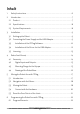
Inhalt 1. Safety Instructions............................................................................................................................ 6 2. Introduction ...........................................................................................................................................7 2.1 Product ...............................................................................................................................................7 2.2 Specifications .................
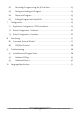
6.2 Recording a Program using the 3D Interface .......................................................... 23 6.3 Saving and Loading of a Program ................................................................................. 23 6.4 Replay of a Program ............................................................................................................ 23 6.5 Editing a Program with GraphEdit ............................................................................... 24 7.
1. Safety Instructions • The Mover4 is designed to be used by adolescents and adults in edutainment and research areas. • The robot must not be used in industrial production facilities of in other continuous operation scenarios. • Do not operate the robot when it is unattended. • The gripping area exposes the risk of bruises to the fingers, especially when using the parallel gripper.
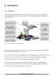
2. Introduction 2.1 Product The Commonplace Robotics Mover4 is a four axis robot for the use in education, entertainment and research environments. He can lift a payload up to 500 g with a reach of 550 mm. Pic. 1: Mover4 and the necessary components The modular set up of the robot connects four joint modules with aluminum profiles. Each joint module contains a servo motor. The front end of the robot, the flange, allows mounting a gripper or another tool.
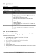
2.2 Specifications Nr of Joints Power Supply Power Consumption Communication Reach Payload Inputs / Outputs Communication 4 servo joints 12V DC at max 5 A Paused: 0,5 A / in motion: < 3 A. Fuse with 3.1 A in base CAN at 500 kBit/s 550 mm including the gripper 500 g At the base of the standard version: 3 digital outputs (5V / 25 mA) and 4 digital Inputs (5V) via D-Sub 9 poles female. At the base of the HeavyDuty version: 4 relay out (24V/1A) and 3 digital in (24V) via D-Sub 9 poles male.
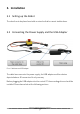
3. Installation 3.1 Setting up the Robot The robot has to be placed on a table or stand so that he cannot tumble down. 3.2 Connecting the Power Supply and the USB Adapter Pic. 2: Cable loom and USB adapter The cable loom connects the power supply, the USB adapter and the robot as depicted above. All connectors fit only one way. Before plugging the USB adapter into the control PC the according drivers should be installed. Please have a look at the following sections.
3.3 Installation of the CPRog Software Insert the CPRog CD into the drive. Depending on your systems configuration the CD menu will open automaticall, or you have to start it manually: D:\.autorun\autorun.exe Choose the first button „Install CPRog” Maybe you have to allow changes to be made on your system. After the installer started you need to choose between English and German as language. Then you need to confirm the license agreement. In the next step you can choose where to install CPRog.
The installation normally takes only few seconds. The installer checks, if DirectX 9.5 is installed. If not it will install theses libraries from the CD or via download. This will take some minutes. The installation of DirectX 9.5 is necessary even if e.g. DirectX 11 is already installed. When finishing the installation you can choose to directly start CPRog. Now you can start CPRog using the link on the desktop or via the start menu.
3.4 Installation of the Driver for the USB Adapter To use the USB-CAN adapter the according driver from PEAK Systeme GmbH have to be installed. They can be found on the CPRog CD. The driver installation should be done before plugging the adapter in! With Windows7 the installation does not pose any problems, with Windows XP please follow the PEAK documentation. This is found on the CD in directory \PeakPCAN\PDF. Insert the CPRog CD into the drive.
Follow the installation assistant. Choose the driver for „PCAN-USB“Adapter. 3.5 Licensing The CPRog software needs a license key to start. This key, an XML file, has to be stored in the directory \CPRog\Data\License The CPRog installer copies the key Demo.xml to the directory. With this key CPRog starts in demo mode. The runtime is limited to 10 minutes, afterwards you need to restart CPRog. Your get your personal key via mail. Copy this key in the license directory.
4. Robor Arm Mover4 4.1 Geometry Pic. 3: Mover4 simplified side view The picture shows the joints length of the Mover4 robot arm. Including the gripper the arm reaches 550 mm. CPRog offers functionalities to limit the workspace, see section 8.2.
4.2 Digital Inputs and Outputs The robot base shows a D-Sub plug with several digital inputs and outputs. The pin assignment for the versions „Standard“ and „HeavyDuty“ are shown below. D-Sub Female: View from the outside on the pins. Male according mirrored.
Pin1: Pin2 Pin3: Pin4: Pin5: Pin 6: Pic. 5: Drawing of the flange 4.4 Drawing of the Robot Base The robot can be mounted using the M4 through holes. Pic. 6: Drawing of the robot base plate 16 12V, max 0.
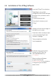
5. Moving the Robot Arm with CPRog 5.1 Introduction The CPRog programming environment allows to control and program the Mover robot. Both online and offline working is possible. Pic. 7: Programmoberfläche von CPRog In the upper area the three ribbons “Scene”, “Motion” and “Programming” provide access to the main functionalities. On the left corner information on the robots current state are provided.
5.
rotation is defined with the B commands. In „Cartesian Tool” mode the robot moves aligned to the current tool coordinate system. The override scales the motion speed between 0 and 100%. Pic. 9: Buttons to jog the robot in cartesian mode. In joint mode the buttons change to the axis A1 to A4. While jogging in cartesian mode virtual walls can be switched on to limit the motion and thereby avoiding e.g. collisions. See section 7 for details.
5.4 Connect with the Hardware The real robot can be controlled in the same way as the simulated one, only the hardware has to be connected before: connect, reset errors and enable motors. Prerequisites are that the robot is connected via the USB-CAN adapter and the robots supply is running (plugged in, switched on and emergency button released). Pic. 11: Buttons to connect to the hardware, reset the errors and enable the motors Step 1: Connect with the hardware.
5.5 Reset the Zero Points of the Joints The joint modules of the Mover4 store the last joint value in their memory, so the robot is aware of his current position after being switched on. But if these values are not corret, the joints need to be calibrated. Reasons may be: • Turning the joints while the robot is without power supply • Stopping the robot with the emergency stop during a motion • … To calibrate the robot it has to be jogged into a perpendicular position using the joint mode.
6. Programming the Robot Arm with CPRog 6.1 Program Elements A Mover4 robot program is build out of the following 9 commands: Lin Joint Relative Wait DigitalOut Loop If-Then-Else ExternalMotion The robot moves on a straight line from the current position to the target position. The velocity is defined in mm/s. Interpolates the axis from the current position to the target position in joint coordinates. Velocity is defined as percentage of the maximum joint rotational velocity.
6.2 Recording a Program using the 3D Interface Using the 3D screen a program can be recorded using the joypad or the buttons. Joypad: Every time the X button on the joypad is pressed a linear command to the current robot position is recorded. If necessary a command to open or close the gripper is added, together with a short break. A sound indicated that the point was recorded. Program Buttons: If there are still commands in the memory, they can be deleted using the Delete button.
6.5 Editing a Program with GraphEdit The button Programming/Editor opens a graphical program editor. This editor allows in a puzzle visualization to adapt and create programs. Pic. 13: Graphical program editor In the upper left area common elements are found, Undo/Redo and Load/SaIve. Two further buttons need explanaition: • The dust bin deletes the selected puzzle piece • The light bulb updates the program on the current robot to the updated version. It also saves the program.
7. Configuration 7.1 Application Configuration: CPRFrontend.xml The application configuration can be done by adapting the parameters in the XML file CPRFrontend.xml in the CPRog directory, e.g. c:\CPRog\ 7.1.1 Language The language for the next start of CPRog is defined by the line Possible choices are DE and EN. 7.1.2 Camera Position in CPRog The initial position of the view camera is defined in the line: PAGE 267.2 Robot Configuration - Software For each robot in the CPRog simulation a XML config file exists, e.g. C:\CPRog\Data\Robots\CPRFour\CPRFour.xml for the Mover4. Definition for the velocities in Jog mode: A virtual cell can be defined as a safety space the robot cannot leave in Cartesian mode: PAGE 278. Interfacing 8.1 Command „External Motion“ Using the „External Motion“ command it is easy to integrate and external control, e.g. a vision system. When the robot reaches this command in program replay he hands control over to the external program. He gets connected via an IP connection defined by IP address and port. The scale parameter adapts the velocity.
The parameter Scale adapts the velocity. When the last answer from the server is older then 500 ms the robot does not move. An Java/Eclipse example program can be found at https://www.github.com/CPR-Robots It demonstrates the set up of the communication an approaching a position. 8.2 CAN-Bus Protocol Further information on the joint controller and the CAN protocol can be found in the module documentation. Get in touch with CPR to get this documentation: info@cpr-robots.com 9.
Program does not start, error message e.g. „The Application could not be initialized correctly (0xc0000135). “ Program does not start, error message: "CPRog has encountered a problem and needs to close”. Program does not start, error message: „CPRog does not work any more” Is the Microsoft .NETFramework missing? Install the current .NET framework from the Microsoft homepage Is and DirectX file missing? These files are necessary for joypad and audio functionalities.
9.3 Hardware Mover4 Error Possible Cause Measures Position error: the robot does not proceed tot he same positions as before. The robot can loose its joint values due to unexpected power loss or motions of the joints when the robot is switched off. The gripper does not open any more The gripper is controlled via the digital outputs 4 (open/close) and 5 (activated?).
10. Language Specification The following nine commands can be combined to form a robot program. A program is and XML file that starts with the lines Then the commands follow, the program closes with the line Command Reference PAGE 32© Commonplace Robotics November 2012