
Installation Guide


8
Installation (continued)
5
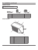
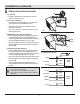
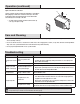
Making the electrical connections
Junction Box
□ Follow the wiring instructions given below to make the
electrical connections. (Fig. 1).
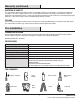
Surface Conduit Mount
□ Remove desired conduit plug (B) from one of the xture’s
sides from the where conduit will enter. (Fig. 2)
□ Make wiring connections inside the xture as per the
instructions given below.
□ If necessary, strip 3/8 in. of insulation from junction box or
xture (A) wires (Fig. 1).
ON/OFF Wiring (Non Dimming) Method:
□ Connect the xture black wire to the supply black wire ((+)
line), and xture white wire to the supply white wire ((-)
common) by twisting the exposed wires together and using
the wire nuts (BB). Ensure there are no loose wires.
□ Connect the supply ground wire to the green xture ground
wire by twisting the exposed wires together and using the
wire nuts (BB).
0-10V Dimmable Wiring Method:
□ Connect the xture black wire to the supply black wire ((+)
line), and xture white wire to the supply white wire ((-)
common) by twisting the exposed wires together and using
the wire nuts (BB). Ensure there are no loose wires.
□ Connect the supply ground wire to the green xture ground
wire by twisting the exposed wires together and using the
wire nuts (BB).
□ Connect the purple wire to the (V+) DIM wire and the
gray wire with (V-) DIM wire by twisting the exposed wire
together.
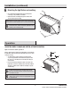
NOTE: Hold stripped ends near each other and align any
frayed strands (do not twist wires).
Push the wires into wire nut (BB) and use your ngers to
twist the wire nut clockwise until tight. Check for tightness by
pulling wires.
(+) Line
Black
White
Lighting
Fixture
Green
(-) Common
Ground
3/8 in.
Non-Dimming Wiring Diagram
(+) Line
Black
White
Lighting
Fixture
Green
(-) Common
Purple
(+)DIM V+
Gray
(-)DIM V-
Ground
0−10V Dimming Wiring Diagram
Fig. 1
BB
Fig. 2
B
BB
D