
Technical data


ACCESSORIES
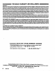
PULSE METER
223-645
For Gallon/Quart Pint
TECHNICAL DATA
E/ecfrksl
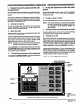
CAUTION
To avoid damaging the electronic components of
the pulse meter control (1) :
1. Do not lay anything on the
eleCtrOniC
controt.
2. Be sure the open side of the electronic control
faces up if you lay it down.
3. Do not twist or force parts. Align parts properly
as instructed.
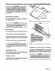
1. Shut off the power to the pump(s) and relieve
fluid pressure.
2. Remove the screws. Lift off the electronic
control.
3. Install a new metering unit (2) and/or electronic
control (1). Align the notches on the underside
of the electronic control with the cutaways in the
top of the meterlng unit. Use the new screws
and torque them oppositely and evenly to
lo-12 in-lb (1.2-l .4 N.m).
Input Voltage . . . . . . . . . . . . . 15 V Maximum
Current Loop Output . . . . .4 milliamps OFF
10 milllamps ON
Hydraulk
Flow.. . . . . . . . . . . . . . 12gpm Maximum
(45.6 Lltedmin Maximum)
Max. Operating Pressure . 1566 psi (105 bar)
Inlet/Outlet. . . . . . . . . . . . l/2 npt
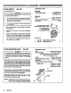
REPLACEMENT SCREWS ’
INCLUDED WITH ITEMS 1 AND 2
TORQUE OPPOSITELY
AND EVENLY TO
lo-12IN-LB(1.2-1.4
N.m)
PARTS LIST
1
223-655 ELECTRONIC CONTROL
2 222-661 METERING UNtT
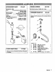
FLUID SOLENOID VALVE
215-487
WARNING
electric shock, turn off the con-
trol and disconnect the power supply cord from the
outlet before checking for loose~or shorted wires,
and before servicing the meters, or solenoid
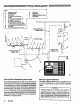
The solenoid valve is normally closed; foreign matter
could hold the valve open, preventing tt from stop-
ping the fluid flow. If that happens, stop the,pump,
open the dispensing valve controlled by the solenoid
valve to relieve line pressure, and close the shutoff
valve ahead of the solenoid valve.
To clean the solenoid valve, unscrewthe nut, remove
the operator and unscrew the piston from the body.
Clean the pans and the seat In the body. Blow alr into
the body to clear the fluid passageways.
Reassemble thevalveanddispensefluid tosee lfthe
held-open condition has been corrected. If It has
not, replace the solenoid valve.
NOTE: Dispense fluid at the dispensing valve con-
trolled by the cleaned or replaced solenoid
valve until all air Is purged from the system.
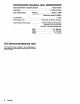
TECHNICAL DATA
Type . . . . . . . . . . 2 way normally closed
Electrical Rating
. . . . . . . . . .
26 V DC, 0.46 amp
NOTE: provides minimum current draw
when operated at 24 V DC
Coil Insulation . . . . . . . . . Class H
Leads . . . . . . . . . . . . . . . . . . . 16AWGx16in.lona
Maximum Working Pressure. 3CCO psi (207 ba5
Inlet/Outlet . . . . . . . . . .
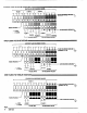
Minimum Actuation Volts Required
l/2 npt
. . . . . . . . . .
20
Wirina Gauoe Reauired for
Lerigth of-Run ’
. . . . . . . . . .
16AWGupto300ft.
16AWGupto566ft.
14AWGuptolCGOft.
NUT
OPERATOR
BODY
IN
6
308-036