
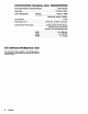
Technical data
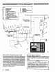
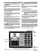

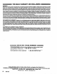

TYPICAL INSTALLATION
KEY
Dispensing Control
Drain Sack Tube
Pump Intake Vaive
Supply Tank
Air Shutoff Valve. Bleed type
Air Filter
Air Solenoid Valve, P/N 215-407
Air Regulator, P/N 202-156
Pump
Pulse Meter. P/N 223-645
Pressure Relief IGI P/N 207-221,
l-1/2 npt (m x f).%U psi Max WPR
Fluid Shutoff Valve. P/N 108-458. 1R
Fluid Filter
Fluid Solenoid Valve, PIN 215-487
tlsady Llghl
Dispense Vahre
T
V
ybeHo~ (3 to 8 It long)
FLUID
LINE
r---
1
M
FLUID SOLtNOlD
I r-L-l
SIGNAL LINE
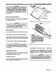
How the Fluid Commander system works
The operator programs the control unit by selecting the
appropriate fluid and station and then setting the quantity
to be dispensed. When the DISPENSE key Is depressed
by the operator, the Control unit energlzes the respective
air and fluid solenoid valves. As the fluid is dispensed by
the service person, the pulse unit sends pulses to the con-
trol unit in proportion to the amount flowing through it.
When the number of pulses counted by the control unit is
equivalent to the preset quantity, the air and fluid solenoid
valves shut off. Refer to OPERATION for more detailed in-
formation on using the system.
About the -pica1 Installation
The TYPICAL INSTALLATION is only a guideline for a ba-
sic system, showing just one fluid. Your Grace sales rep-
resentative can help you design a system to suit your
needs.
WARNING
A Pressure Relief Kit is required in your system
to
reduce the risk of serious bodily Injury such as
splashing fluid in the eyes or on the skin, which can
occur if excessive system pressure ruptures the
lines and components. Install the kit as shown in the
Typical Installation Drawing. Order Grace apart No.
207-221. See page 7.
2
306-036