
Specifications

- 8 -
3. Wiring
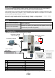
3.1 Power Supply Wiring
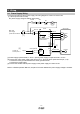
Connect the actuator and driver power supply. This wiring diagram is common for each mode.
(1) LECSA (Incremental encoder)
EX.) Power supply voltage is 200VAC single phase
L1
L2
Main circuit
power supply
1-phase 200 to 230VAC
P
C
+24V
0V
U
V
W
Control circuit power supply
CNP1
CNP2
U
V
W
M
Motor
Encoder
CN2
Encoder cable
MCNFB
Servo motorServo amplifier
RA
OFFTrouble
MC
ON
MC
SK
(Note 5)
Forced stop
(Note 6)
Circuit protector
(Note 4)
(Note 2)
24VDC (Note 7)
(Note 1)
Built-in regenerative
resistor
[1] Power supply input terminals, L
1
and L
2
: Specify power supply to input terminals L
1
and L
2
.
[2] Connect the motor power supply input terminal (U, V, W) to the driver power terminal (U, V, W).
Connect the motor ground terminal to the driver ground terminal.
Connect the encoder cable.
[3] Connect the 24VDC external power supply to the power supply for control circuit.
Refer to “LECSA Operation Manual”, Chapter 3 for further details if the power supply voltage is 100VAC.
Drive
r
[1]
[3]
[2]