
Specifications

- 6 -
Introduction
It is recommended that the operator read the operation manual for LECSA prior to use. For the handling
and details of other equipment, please refer to the operation manual for said equipment.
Check that the main circuit power supply (AC100V/AC200V) and controller circuit power supply (24V) are
wired correctly. Please refer to chapter 3.1 of the “LECSA Operation Manual” and chapter 2 of the “LECSA
Operation Manual (Simplified Edition)” for details.
When setup software (MR Configurator) is used, the LECSA□-□ model selection is required. Select '
MR-JN-A ' through “Model Selection" - "System settings" - "Setup" and "Project name".
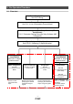
Terms
Position control mode (pulse)
Control the motor rotation speed and direction with pulse train and
perform positioning.
Positioning mode (Point table)
Set the positioning data, rotation speed, Acceleration/Deceleration time
constant of the drivers point table and execute ON/OFF control of the
positioning operation using the I/O signals (a maximum of 7 points can
be used for the point table configuration).
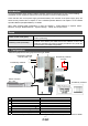
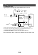
1. Configuration
Minimum equipment and wiring requirements to get started
1 Driver LECSA*-S*
2 Motor cable LE-CSM-***
3 Encoder cable LE-CSE-***
I/O connector LE-CSNA 4
I/O cable LEC-CSNA-1
5 USB cable LEC-MR-J3USB
6 Setup software (MR Configurator
TM
) LEC-MR-SETUP221
7 Main circuit power supply connector CNP1 (Accessory)
8 Control circuit power supply connector CNP2 (Accessory)
Note) The lock cable option is not shown on this drawing. Refer to the “LECSA Operation Manual” for details.
8
3
4
6
2
1
7
Electric Actuators
Ex) LEF
PC
Provided by customer
24 VDC
Provided by customer
100V AC /200 V AC
Provided by customer
Provided by customer