
Specifications

- 66 -
7.4 Point table method
Positioning operation can be executed by setting the position data, rotation speed, acceleration time constant,
deceleration time constant to the point table data. (The maximum points that can be set in point table is 7.)
7.4.1 Operation Instruction of Point Table system
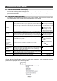
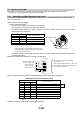
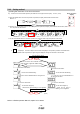
Select the point table No. represented by the values of DI0, DI1 and DI2. Start the operation by selecting ST1
or ST2.
Positioning
mode
Device Symbol
Connector
pin No.
Functions/Applications
I/O
division
CP CL
Point table No.
/Program No.
selection 1
DI0 CN1-5 <In point table method>
The point table No. and the home position return
mode are selected by DI0 to DI2.
<In program method>
The program No. is selected by DI0 to DI2.
DI-1
(Note)
Device
Selection description
DI1 CN1-23 DI2 DI1 DI0 Point table method DI-1
0 0 0 Home position return mode
0 0 1 Point table No. 1
0 1 0 Point table No. 2
0 1 1 Point table No. 3
Point table No.
/Program No.
selection 2
1 0 0 Point table No. 4
DI2 1 0 1 Point table No. 5 DI-1
1 1 0 Point table No. 6
1 1 1 Point table No. 7
Point table No.
/Program No.
selection 3
Note. 0: off
1: on
Program
input 1
PI1 Turn PI1 on to resume the step stopped by the
SYNC (1) command in the program.
DI-1
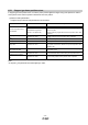
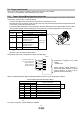
Point table No.
Position data
[×10
STM
μm]
Servo motor
speed [r/min]
Acceleration
time constant
[ms]
Deceleration
time constant
[ms]
Dwell
[ms]
Auxiliary
function
1 5.00 3000 100 150 100 1
2 -6.00 2000 100 100 0 3
3 3.00 3000 50 50 0 0 (Note)
Note. Always set "0" or "2" to the auxiliary function in the last point table among the consecutive point tables.
0: When point table is used in absolute value command system
2: When point table is used in incremental value command system