
Specifications

- 46 -
Note
One example of signal allocation will be shown using the Setup Software. It is expected that the user
will follow similar method applicable to the relevant signals that need reallocation.
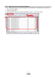
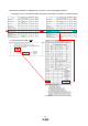
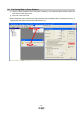
(1) Example of Signal Allocation using the setup software
When changing pins CN1-7 from Reverse rotation start (ST2) to point table no./program no. selection 3 (DI2):
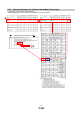
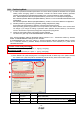
① Change PD12 from 0808 to 2E08 in the I/O settings tab.
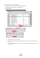
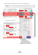
② Click “Write All”
③ Cycle the power off, and then on for the parameters to be enabled.
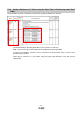
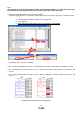
* Complete pin CN1-7 allocation separately.
* See “LECSA Operation Manual”,section 4.4.2 for details on allocation of input signals to pins CN1-3 - CN1-8
* See “LECSA Operation Manual”,section 4.4.2 for details on allocation of input signals to pins CN1-23 and
CN1-25
* See “LECSA Operation Manual”,section 4.4.2 for details on allocation of output signals to pins CN1-9 and
CN1-12
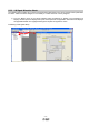
Schematics showing typical 3 point positioning
0808
→2E08
①
②