
Specifications

- 39 -
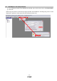
5.5 Changing I/O Signal Allocation
Input/output signal assignment can be changed as appropriate from initial settings. There may be cases
when changes to the Input/output signal assignment are required for actuator operation.
Please be aware that any changes will alter signals entered as initial settings.
Please allocate it according to your system specification.
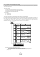
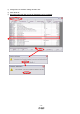
*When configuring PD**, please set parameter write inhibit [PA19] to 00E.
See “LECSA Operation Manual”,section 4.4 for details.
Set parameters related to I/O: [PD02] to [PD18]
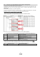
5.5.1 Initial I/O Signal Allocation
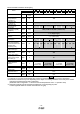
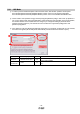
(1) Position control mode (pulse input):
The initial (Default) allocation of I/O signals is shown below.
See “LECSA Operation Manual”,section 3.5 and “LECSA Operation Manual”,section 3.6 for details
regarding signals.
See “LECSA Operation Manual”,section 4.4.2 for parameter configuration values.
※ Pins CN1-23 and CN1-25 are pulse input terminals. These cannot be allocated as any other input
signals.
※ Pins CN1-3 - CN1-8 (input signals) and CN1-9 - CN1-12 (output signals) can be allocated as
current SYNC (NPN) interface and current SOURCE (PNP) interface wiring and I/O signal
allocation.
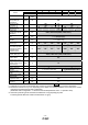
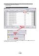
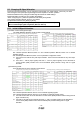
(2) Positioning mode:
The initial allocation of the I/O signals is shown below.
See “LECSA Operation Manual”,section 13.2.3 for details regarding signals.
See “LECSA Operation Manual”,section 4.4.2 for details on parameter setting values.
※ Pins CN1-23 and CN1-25 can be allocated in current SYNC (NPN) interface interface wiring and I/O
signal allocation only.
※ Pins CN1-3 and CN1-8 (input signals) and CN1-9 ~ CN1-12 (output signals) can be allocated in
currect SYNC (NPN) interface and current SOURCE (PNP) interface wiring and I/O signal
allocation.
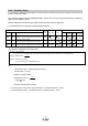
PD02 to PD14 Input signal assignment (CN1-23, CN1-25, CN1-3 to CN1-8)
PD15 to PD18 Output signal assignment (CN1-9 to CN1-12)
Input signal points (6): (position control mode) and initial assignment Output signal points (4) (position control mode) and initial assignment
Input signal points (8): (positioning mode) and initial assignment
Output signal points (4): (positioning mode) and initial assignment