
Specifications

- 34 -
5.3.6 Electronic Gears
It is necessary to adjust the electric gear to convert from the command pulse sent from position unit to the travel
amount of electrical actuator.
See “LECSA Operation Manual (Simplified Edition)”,section 5.3.4 for the recommended values for electronic
gears for each actuator model.
Please configure the electronic gear values according to the customer application.
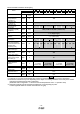
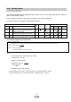
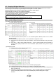
(1) LECSA Parameter Configuration: [PA05], [PA06] and [PA07]
Parameter Control mode
No. Symbol Name
Initial
value
Setting range Unit
Position
Internal
speed
Internal
torque
Positioning
PA05 *FBP Number of command input pulses per revolution
100
0
100 to
500
100
pulse/rev
PA06 CMX
Electronic gear numerator
(Command pulse multiplying factor numerator)
1
1 to 65535
PA07 CDV
Electronic gear denominator
(Command pulse multiplying factor denominator)
1
1 to 65535
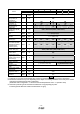
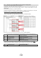
(1) Complete configuration as shown below.
Ex.)
Travel amount per 1 command pulse (P=10μm)
Actuator lead (L = 6mm)
[PA05] = 100 (Initial value)
[PA06]=100×100×10×
=100×100×0.01
=100
[PA07]=6 (Actuator lead (L) [mm])
*In case position control mode, "Travel amount per 1 command pulse"P = 10[um]
*In case positioning mode, "Travel amount per 1 command pulse"P = 1[um]
*[PA05] = 100 (Initial value)
The initial value of 100 corresponds to the "Nomber of command input pulses per revolution" of 10000 [pulses/rev].
* [PA06] = [PA05]×100×P×
* [PA07] = Actuator lead (L) [mm]
P: Travel amount per 1 command pulse [μm]*
1000
1
1000
1