
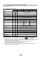
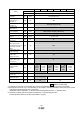
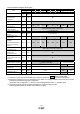
Specifications

- 28 -
LEFB25 LEFB25U LEFB32 LEFB32U LEFB40 LEFB40U
Lead symbol S
Series
Lead 54
Parameter
Para
No
Initial
value
Recommended value
Number of command
input pulses per
revolution
*3.
PA05 100
100
Electronic gear
numerator *3.
PA06 1
100 (Positioning mode: 10)
Electronic gear
denominator *3.
PA07 1
54
Feel length multiplication
(STM) (Multiplier)
PE02 0000
0000 (<1000 stroke)/0001 (>1000 stroke)
Home position return type PE03 0010 □□□3 (Stopper type)
Home position return
direction
PE03 0010
□□1□ (Motor side)
Home position return
Speed (rpm)
PE04 500
66
Home position
return/JOG operation
Accelerationeration/Decel
eration time constants
(msec)
PE07 100
2700
Home position return
position data (μm)
PE08 0
-3000 (<1000 stroke)/-300 (>1000 stroke)
Stopper type home
position return
stopper time (msec)
PE10 100
200
Stopper type home
position return torque
limit value (%)
PE11 15
30
Regenerative option PA02 000 000 (Non)/002 (LEC-MR-RB-032)
Rotation direction
selection
PA14 0
1 (+:
Counter
motors
side)
0 (+:
Counter
motors
side)
1 (+:
Counter
motors
side)
0 (+:
Counter
motors
side)
1 (+:
Counter
motors
side)
0 (+:
Counter
motors
side)
★ Adaptive tuning mode PB01 000 002 000
★ Load to motor inertia
moment ratio
PB06 7
50
★ Machine resonance
suppression filter 1
PB13 4500
400 4500
★ Notch shape selection
1
PB14 000
030 000
★ Parameter setting required.
Differs to initial value
*1. Parameter is set to the recommended value. Please set parameter according to customer application.
*2. Mechanical resonance may occur depending on the shape or mounting orientation of the work piece. Please
change this parameter during initial configuration.
(Parameter initial configuration ⇒ Set the recommended parameter value ⇒ Operation start)
*3. Other than positioning mode: Actuator travel distance at 10 [μm/pulse] per pulse.
Positioning Mode: Minimum actuator travel distance of 1[μm].