
Specifications


- 17 -
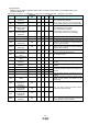
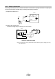
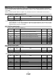
4.4 Torque control mode
(1) [Extension setting parameters (No. PC□□)]
No. Symbol Name Default Unit
PC01 STA
Acceleration time constant
0 ms
PC02 STB
Deceleration time constant
0 ms
PC05 SC0
Internal speed limit 0
0 r/min
PC06 SC1
Internal speed limit 1
100 r/min
PC07 SC2
Internal speed limit 2
500 r/min
PC08 SC3
Internal speed limit 3
1000 r/min
PC31 SC4
Internal speed limit 4
[Applied]
200 r/min
PC32 SC5
Internal speed limit 5
[Applied]
300 r/min
PC33 SC6
Internal speed limit 6
[Applied]
500 r/min
PC34 SC7
Internal speed limit 7
[Applied]
800 r/min
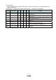
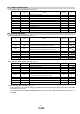
4.5 Positioning mode
(1) [Basic settings parameters (No.PA□□)]
No. Symbol Name Initial value Unit
PA05 FBP Number of command input pulses per revolution
100 ×100
pulse/rev
PA06 CMX
Electronic gear numerator
(Command input pulse multiplying factor numerator)
1
PA07 CDV
Electronic gear denominator
(Command input pulse multiplying factor denominator)
1
PA08 ATU Auto tuning mode
001h
PA09 RSP Auto tuning response
6
PA10 INP In-position range
100 pulse
PA13 PLSS Command input pulse form
000h
PA14 POL Rotation direction selection
0
(2) [Positioning setting parameters (No. PE□□)]
No. Symbol Name Initial value Unit
PE01 CTY
Command mode selection
0000h
PE02 FTY
Feeding function selection
0000h
PE03 ZTY
Home position return type
0010h
PE04 ZRF
Home position return speed
500 r/min
PE06 ZST
Home position shift distance
0 μm
PE07 FTS
Home position return/JOG operation
Accelerationeration/Deceleration time constants
100 ms
PE08 ZPS
Home position return position data
0 ×10
STM
μm
PE13 JOG
JOG speed
100 r/min
PE16 LMPL
Software limit +
0 ×10
STM
μm
PE18 LMNL
Software limit -
0 ×10
STM
μm
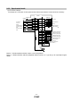
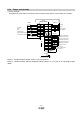
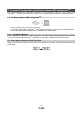
(3) [I/O setting parameters (No. PD□□)]
These parameters are set when changing the assignment of the input/output signal and using the point table
at a maximum of 7 points.
See “LECSA Operation Manual (Simplified Edition)”,section 5.5 and “LECSA Operation Manual”,section 4.4
for details.