
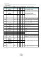
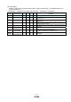
Specifications


- 12 -
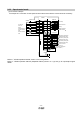
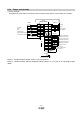
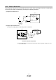
3.2.2 Speed control mode
(1) Connection example
An example of a connection for the speed control mode is shown below. Connect wires as necessary.
LZ
Plate
Servo amplifier
Trouble (Note 6)
Electromagnetic
brake interlock
9ALM
10 SA
11 RD
12 MBR
CN1
Speed reached
Ready
Encoder A-phase pulse
(differential line driver)
15 LA
16 LAR
17 LB
18 LBR
14 LG
21 OP
SD
2m max.
Encoder B-phase pulse
(differential line driver)
Control common
Encoder Z-phase pulse
(open collector)
Encoder Z-phase pulse
(differential line driver)
19
20 LZR
CN1
1
13
DICOM
DOCOM
10m max.
USB cable
(option)
CN3
MR Configurator
Personal
computer
24VDC
RA1
RA2
RA3
RA4
8
4
3
7
Forced stop
Servo-on
Reset
Forward rotation
start
Reverse rotation
start
(Note 3, 5)
5
6
Speed selection 1
EM1
SON
RES
ST1
ST2
SP1
(Note 9,
10, 12)
(Note 4, 9)
(Note 7)
(Note 2)
(Note 9, 11)
10m max.
(Note 1)
(Note 8)
(Note 7)
Control common
CNP1
Refer to“LECSA Operation Manual”,section 3.2 for wiring details.
Refer to “LECSA Operation Manual (Simplified Edition)”,section 3.2.1 (2) and (3) for input/output signal
details.
Drive
r