Doc. no.
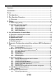
Contents Contents ......................................................................................................1 Introduction.................................................................................................6 Terms ...........................................................................................................6 1. Configuration.........................................................................................6 2. Pre-Operation Procedure...............................
5.5.2 5.5.3 5.5.4 Table) 5.5.5 Signal Allocation using Setup Software............................................................ 40 Allocation Examples for Position Control Mode (Pulse Input) ....................... 41 Setting a Maximum of 7 Points using the Point Table in Positioning mode (Point 43 I/O Signal Allocation Check................................................................................ 47 5.6 Positioning Mode in Setup Software ..........................................................
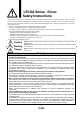
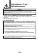
LECSA Series / Driver Safety Instructions These safety instructions are intended to prevent hazardous situations and/or equipment damage. These instructions indicate the level of potential hazard with the labels of “Caution,” “Warning” or “Danger”. They are all important notes for safety and must be followed in addition to International Standards (ISO/IEC), Japan Industrial Standards (JIS) *1.) and other safety regulations*2.).
3) An application which could have negative effects on people, property, or animals requiring special safety analysis. 4) Use in an interlock circuit, which requires the provision of double interlock for possible failure by using a mechanical protective function, and periodical checks to confirm proper operation. Note that the CAUTION level may lead to a serious consequence according to conditions. Please follow the instructions of both levels because they are important to personnel safety.
LECSA Series / Driver Safety Instructions Caution The product is provided for use in manufacturing industries. The product herein described is basically provided for peaceful use in manufacturing industries. If considering using the product in other industries; consult SMC beforehand and exchange specifications or a contract if necessary. If anything is unclear, contact your nearest sales branch.
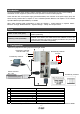
Introduction It is recommended that the operator read the operation manual for LECSA prior to use. For the handling and details of other equipment, please refer to the operation manual for said equipment. Check that the main circuit power supply (AC100V/AC200V) and controller circuit power supply (24V) are wired correctly. Please refer to chapter 3.1 of the “LECSA Operation Manual” and chapter 2 of the “LECSA Operation Manual (Simplified Edition)” for details.
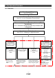
2. Pre-Operation Procedure 2.1 Flow chart Power Supply Wiring See P8 “3. Wiring” Parameter setting See P16 “4. List of Parameters for each Mode” Parameter Settings using the Setup Software (MR Configurator) P18 “5. Parameter Settings using the Setup Software (MR Configurator)” Signal Assignment Configuration See P39 “5.5 Changing I/O Signal Allocation” Home position return Method See P60 “6.Home position return” Home position return Method See P60 ”6. Home position return”.
3. Wiring 3.1 Power Supply Wiring Connect the actuator and driver power supply. This wiring diagram is common for each mode. (1) LECSA (Incremental encoder) EX.
3.2 I/O signal connection example Detail of connection examples for the I/O signals of the driver. 3.2.1 Position control mode (1) Connection example An example of a connection for the position control mode is shown below. Connect wires as necessary. This is a wiring example using the Mitsubishi Electric (FX3U-□□MT/ES) PLC for position control. (Connection example of the open collector system) See“LECSA Operation Manual” and the technical data disclosed the PLC and positioning unit operation manuals.
(2) Input signal Position control mode: P, Speed control mode: S, Torque control mode: T, Point table method: CP, Program method: CL ●: Automatic ON can be set, ○: Initial setting, □: Assignment is available with parameter,-: Assignment is not available Symbol PP NP PG NG SON RES Device name Forward rotation pulse train Reverse rotation pulse train Differential forward rotation pulse train Differential reverse rotation pulse train Servo-on Reset Automatic ON P S T CP/ CL ‐ ○ ‐ ‐ ‐ ‐ ○ ‐ ‐
(3) Output signal Position control mode: P, Speed control mode: S, Torque control mode: T, Point table method: CP, Program method: CL ○: Initial setting, □: Assignment is available with parameter,-: Assignment is not available CP/ Symbol Device name P S T Function CL This signal turns off while alarm is generated.
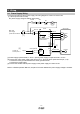
3.2.2 Speed control mode (1) Connection example An example of a connection for the speed control mode is shown below. Connect wires as necessary. Driver Servo amplifier 24VDC (Note 4, 9) (Note 7) (Note 7) CN1 1 DOCOM 13 EM1 8 SON 4 RES 3 SP1 5 6 ST1 ST2 7 DICOM (Note 3, 5) Forced stop (Note 9, 10, 12) Servo-on Reset Speed selection 1 Forward rotation start Reverse rotation start (Note 8) MR Configurator 10m max.
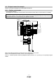
3.2.3 Torque control mode (1) Wiring example An example of a connection for the torque control mode is shown below. Connect wires as necessary. Driver Servo amplifier (Note 6) (Note 6) 24VDC (Note 4, 8) CN1 CN1 DICOM 1 9 DOCOM 13 11 (Note 3) Forced stop 8 EM1 Servo-on 4 SON 12 (Note 8, 9) Reset 3 RES Speed selection 1 5 SP1 Forward rotation selection 7 RS1 Reverse rotation selection 6 RS2 19 10m max.
3.2.4 Positioning mode (1) Connection example An example of a connection for the position control mode is shown below. Connect wires as necessary. Servo amplifier Driver 24VDC (Note 4, 9) (Note 3, 5) Forced stop Servo-on Automatic/manual selection (Note 9, 10, 12) Proximity dog Point table No./Program No. selection 1 Point table No./Program No.
3.2.5 Source I/O interfaces Source type I/O interfaces can be used with this driver. If used, all DI-1 input signals and DO-1 output signals are source type signals. Complete wiring according to the following interfaces. (1) Digital input interface DI-1 Driver Servo amplifier SON, Approx. 5.6k etc. Switch DICOM 24VDC 10% 200mA Approx. 5mA VCES 1.0V ICEO 100 A (2) Digital output interface DO-1 A maximum voltage drop of 2.6V may occur in the driver. Driver Servo amplifier ALM, etc.
4. List of Parameters for each Mode These parameters require configuration in each control mode. Please configure parameters as required. Refer to “LECSA Operation Manual (Simplified Edition)”,section 5.3 and “LECSA Operation Manual”,chapter 4 for details. Refer to “LECSA Operation Manual”,chapter 4 for parameters which are not disclosed in this document. 4.1 Parameters common to each mode (1) [Basic settings parameters (No.PA□□)] No.
4.4 Torque control mode (1) [Extension setting parameters (No. PC□□)] No.
5. Parameter Configuration using Setup software (MR ConfiguratorTM) This section describes the configuration procedure for main parameters using the setup software (MR ConfiguratorTM: LEC-MR-SETUP221E). See chapter 4 of the “LECSA Operation Manual” for parameter details. 5.1 PC Setup software (MR ConfiguratorTM) *1 Setup software version C5 or above is required. *2 The setup software (MR ConfiguratorTM : LEC-MR-SETUP221E)must be purchased as an additional item.
5.2.1 Start up the Setup software (MR ConfiguratorTM) ① Connect the PC and LECSA using the USB cable. ② Turn on the power of the LECSA. ③ Start application “SETUP221E”. Once the application starts, the screen below will be displayed.
5.2.2 Driver ON LINE Check Check that the driver is enabled (ON LINE). If the driver is not enabled, check the wiring and power supply voltage. 5.2.3 Help Function By selecting “MR Configurator Help” in “Help” from any window of the setup software, a “HELP” screen will be shown as shown below.
5.2.4 “System Settings” ① From “Setup” menu select “System Settings”, the “System Settings” window will be displayed. 5.2.5 ① ② ③ ④ ⑤ ⑥ Model Selection The Mitsubishi Electric Corporation series will be displayed in the model selection list. Please select MR-JN-A if using the LECSA. Please select “servo amplifier connection USB” as the communication device. Select “Online” in the connection selection menu. Click OK. Click OK.
5.2.6 Parameter Upload Upload the current parameters from the driver to the software. ① From the “Parameters” menu select “Parameter list” the “parameter setting” window will open. ② Click the “Read All” button. ③ If a Servo-alarm occurs, click “OK”. ① ② ③ The parameters PA, PB, PC, PD and PE can be set using the following tabs.
5.3 Parameter Settings 5.3.1 Settings to Allow Configuration of all Parameters To enable settings for all parameters for this driver PA19 needs to be set to 00E. ① Select “Basic settings (list)” tab and change “PA19” Value to “00E”. ② Select “Write All”. ③ Cycle the poweroff, then on for parameters for this driver to be enabled.
5.3.2 “Control mode selection” When using Position control mode (pulse input) Change the “control mode” from “Position control mode (pulse input)” to “Positioning (Point table)”. ① From the “Basic settings” tab and “Parameter Setting” window from the drop down selection “Control mode selection” select “Positioning (Point table) ① When using Position control mode (pulse input) ② Parameter PA01 will change to 000 under the “Basic settings (list)” tab.
② ③ ④ ⑤ Please be aware of the following when changing parameters. ・For each parameter type, all have the feature that “parameters are enabled after the power supply is cycled after configuration” (Driver data will not come into effect until the power supply has been turned off). ・ The parameter writing range to the driver differs between “Write” and “Write All”. ① “Write”: The parameter for the applicable frame will be written to the driver. ② “Write All”: All parameters will be written to the driver.
5.3.3 Parameter Configuration Method Set the parameters for applicable actuator. Refer to “LECSA Operation Manual (Simplified Edition)”,section 5.4.3 for recommended parameter values for SMC supplied actuators. However, when using position control mode (pulse input), do not alter parameters PE02/PE03/PE04/PE07/PE08/ PE10/PE11 from their initial values (Only change these parameters for Positioning mode (point table/program method)).
5.3.4 Recommended Parameter Values by Actuator Model Please change the parameter values according to the customer application. See section 4 of the “LECSA Operation Manual” for details. Recommended Parameter Values [LEF] LEFS25 Series Parameter Number of command input pulses per revolution *3. LEFS32 LEFS40 Lead symbol H A B H A B H A B Lead 20 12 6 24 16 8 30 20 10 30 20 10 No Initial value Recommended Value PA05 100 100 Para Electronic gear numerator *3.
LEFB25 Series Parameter LEFB25U LEFB32 LEFB32U Lead symbol S Lead 54 LEFB40 No Initial value Recommended value PA05 100 100 PA06 1 100 (Positioning mode: 10) PA07 1 54 PE02 0000 0000 (<1000 stroke)/0001 (>1000 stroke) PE03 0010 □□□3 (Stopper type) PE03 0010 □□1□ (Motor side) PE04 500 66 PE07 100 2700 PE08 0 -3000 (<1000 stroke)/-300 (>1000 stroke) PE10 100 200 PE11 15 30 PA02 000 Para LEFB40U Number of command input pulses per revolution *3.
Recommended Parameter Values [LEJ] Series Parameter Lead symbol Lead Para.
Recommended Parameter Values [LEY] LEY25/LEYG25 Series Parameter Number of command input pulses per revolution *3. Electronic gear numerator *3. Electronic gear denominator *3.
LEY63 Series Parameter Number of command input pulses per revolution *3. Electronic gear numerator *3. Electronic gear denominator *3.
5.3.5 Position control mode (pulse input) It is required to set the command input pulse form dependent on the upper unit pulse train when using the Position control mode (pulse input).
① Change PA13 in the Basic settings list tab to 201. ② Click “Write All”. ③ Cycle the power off, then on for the Parameters to be activated.
5.3.6 Electronic Gears It is necessary to adjust the electric gear to convert from the command pulse sent from position unit to the travel amount of electrical actuator. See “LECSA Operation Manual (Simplified Edition)”,section 5.3.4 for the recommended values for electronic gears for each actuator model. Please configure the electronic gear values according to the customer application. (1) LECSA Parameter Configuration: [PA05], [PA06] and [PA07] Parameter No.
5.3.7 Automatic Input Signal ON Selection Parameter Configuration Configure the input signal automatic ON selection parameter. The parameter “PD01:Input signal automatic ON selection” settings, defines which input signals will turn ON automatically when the control circuit power supplyis turned on., doing this allows additional I/O signal selection range. Please allocate it according to your system specification. Configure the automatic ON selection in parameter [PD01], or configure the I/O signal layout.
* Enabling “Stroke end” (LSP, LSN) , “Forced stop” (EM1) and “Servo-on” (SON) Signals ① Set to PD01 to 0C24 in the I/O setting tab. ② Select “Write All”. ③ Cycle the power off, then for thechanged Parameters to be enabled. ① ② * In this configuration, the stroke end (LSP, LSN), forced stop (EM1) and servo-on (SON) signals will be ON automatically when the power is turned ON.
5.4 JOG Mode in the Setup Software ① The “JOG Mode” window can be displayed by selecting “Jog” from the “Test” menu in the setup software. ② Click “OK”. (When using this function, all external input signal operation will be diabled. If controlling using a PLC or other upper device, please turn off the power and reset the device before use.
5.4.1 JOG Mode ① In order to prevent accidental impact at the end of the stroke, test actuator operation at low speed. See “LECSA Operation Manual (Simplified Edition)”,section 5.6.2 for motor speed configuration. See “LECSA Operation Manual (Simplified Edition)”,section 5.6.3 for Acceleration/deceleration time. ② Check actuator JOG operation using [Forward (CCW)] and [Reverse (CW)] in JOG mode. (if operation is not correct, please check wiring and parameters).
5.5 Changing I/O Signal Allocation Input/output signal assignment can be changed as appropriate from initial settings. There may be cases when changes to the Input/output signal assignment are required for actuator operation. Please be aware that any changes will alter signals entered as initial settings. Please allocate it according to your system specification. *When configuring PD**, please set parameter write inhibit [PA19] to 00E. See “LECSA Operation Manual”,section 4.4 for details.
5.5.2 Signal Allocation using Setup Software ① The “Parameter Setting” window will be displayed when “parameter list” is selected from the “parameters” menu in the setup software. ② Click the I/O setting tab. ③ When changing the allocation of signals, parameters for “PD02” - “PD18” can be altered.
5.5.3 Allocation Examples for Position Control Mode (Pulse Input) (1) Example of Gain switch (CDP) Settings When changing pin CN1-4 from Servo-on (SON) to Gain switch (CDP).
(2) Symbol allocation using the setup software: Changing pins CN1 – 4 from servo-on (SON) to gain switch (CDP): ① Change PD05 from 0202 to 0211 in the I/O settings tab. ② Select “Write All”. ③ Cycle the power off, then on for the parametersto be enabled.. ② ※ Please allocate pins CN1-4 separately. ※ See “LECSA Operation Manual”,section 4.4.2 for details on allocation of input signals to pins CN1-3 - CN1-8. ※ See “LECSA Operation Manual”,section 4.4.
5.5.4 Setting a Maximum of 7 Points using the Point Table in Positioning mode (Point Table) The point table can reach a maximum of 7 points using input signals DI0, DI1 and DI2. The default allocation, allocates signals DI0 to (CN1-5) and DI1 to (CN1-23). Note – CN1-23 can only be used if the input is configured as current sink NPN 4 points can be specified , however 1 point is reserved for the home position return, 3 points can be specified in the point table.
(1) Example of Allocation of a Maximum of 7 Points in current SYNC (NPN) Interface Changing pin CN1-7 from Reverse rotation start (ST2) to point table no./program no. selection 3 (DI2): ① ① Change PD12 from 0808 to 2E08.
(1) Example of Allocation of a Maximum of 7 Points in current Source (PNP) Interface ① Changing pins CN1-3 from Automatic/manual selection (MD0) to point table no./program no. selection 3 (DI2): ② Changing pins CN1-7 from Reverse rotation start (ST2) to point table no./program no. selection 2 (DI1): ① ② ① Change PD04 from 2003 to 2E03. 2E ② Change PD12 from 0808 to 2D08.
Note One example of signal allocation will be shown using the Setup Software. It is expected that the user will follow similar method applicable to the relevant signals that need reallocation. (1) Example of Signal Allocation using the setup software When changing pins CN1-7 from Reverse rotation start (ST2) to point table no./program no. selection 3 (DI2): ① Change PD12 from 0808 to 2E08 in the I/O settings tab. ② Click “Write All” ③ Cycle the power off, and then on for the parameters to be enabled.
5.5.5 I/O Signal Allocation Check The ON/OFF state (including layout check) and signal names allocated to CN1 can be checked. When parameters for PD02 - PD18 have been changed, It is necessary to confirm these are correctly assigned. ① From the Monitor menu of the Setup Software select Input/Output I/F Display. The Input/Output I/F Display window opens and displays the inputs and outputs that are applicable. The window also displays the applicable MODE.
5.6 Positioning Mode in Setup Software ① Using the Setup Software menu Test select Positioning. The positioning Mode window opens and Test-mode window opensin the. ② Click OK. In the Test-mode (When using this function, external input signal operation will be disabled. When controlling from a PLC or upper device, the power must be turned off and then on.
5.6.1 Positioning Mode ① In order to prevent accidental impact at the end of the stroke, operate the actuator at a low speed initially. When changing speed or movement, increase the values whilst checking operation (Change motorspeed, acceleration/deceleration time, movement distance values if required). See “LECSA Operation Manual (Simplified Edition)”,section 5.6.2 for motorspeed configuration. See “LECSA Operation Manual (Simplified Edition)”,section 5.6.
5.6.2 Motorspeed Configuration ① Motorspeed (r/min) configuration. *R/min (rpm): Indicated motor rotation speed (motor rotations/min) Rotation speed must be between 0 and the allowable speed limit for each actuator. Please be aware that the actuator will not operate if this is set to 0. If the rotation speed is too low, this may cause vibration; check the actuator while changing settings. Movement speed (mm/s) must be converted into rotation speed (r/min).
5.6.3 Acceleration/deceleration Time Configuation < Acceleration/deceleration Time Configuration> ① Acceleration/deceleration time (ms) configuration: The acceleration/deceleration time sets the amount of time (ms) in which a prescribed number of rotations (3000[r/min]) is reached. The acceleration/deceleration time must be set to a value between 0 and the allowable acceleration/deceleration speed for each actuator.
5.6.4 ① ② ③ Move distance Configuration and Operation< Move distance Configuration> Set the move distance [pulse]. Select a value within the stroke range. Actuator position will operate using [Forward (CCW)], [Reverse (CW)]. The position at which power is turned ON will be set as the home position, and the actuator will travel the amount set as move distance (check wiring and parameters If operation is not performed correctly).
5.7 Positioning (Point Table) Operation using the Setup Software This feature is only available in positioning (point table) mode. When positioning using the positioning (point table) mode, the point table (position data, speed data, acceleration time, deceleration time etc.) must be configured. 5.7.1 Point table List ① Using the “Positioning Data” menu in the setup software.
5.7.3 Point table (Position data) Configuration < Position data Configuration> ① For actuators with a stroke less than 1000mm, set parameter PE02 (Feel length multiplication (STM) (Multiplier) ) to 0000 and the STM value to x1. For actuators with a stroke more than 1000mm, set parameter PE02 (Feel length multiplication (STM) (Multiplier) ) to 0001 and the STM value to x10. ② Configure position data (mm). Set to a value within the stroke range.
5.7.4 Point table (Servo Mmotor Speed) Configuration ① Rotation speed configuration: *R/min (rpm): motor command rotation speed (motor rotations/min) Travel speed (mm/s) must be converted into rotation speed (r/min). See below for the conversion formula.
5.7.5 Point Table Configuration (Acceleration time constant/Deceleration time constant) < Acceleration time constant/Deceleration time constant Configuration> ① Acceleration time constant (ms)/Deceleration time constant (ms) configuration: Acceleration/deceleration (mm/s2) must be converted to the acceleration time constant/deceleration time constant (ms). See below for the conversion formula.
5.7.7 Single-Step Feed In Test mode a single step within point table can be executed. ① From the “Test” menu in the setup software select “Single-step Feed”which opens a window for “Single-step feed”. (When using this function, external input signal operation will be disabled. If controlling using a PLC or other upper device, ensure the power is turned off and then on before operation.) ② Select point table number. ③ Press “Start”.
5.8 Saving/Loading Parameters 5.8.1 Saving Parameters ① From the “Project” menu in the setup software select “Save As Project” opens a window “Save As Project”. ② Enter a project name. ③ Click “Save”. Files will be saved to the default folder “C:/Melservo/setup221/*project name* (If the path is changed then, the files will be saved to the new path /*project name*) Files Saved device.prd paramet.prm project.prj point.
5.8.2 To Load saved Parameters ① “Open Project” from the “Project” menu using the setup software The “Open Project” window will open. ② Select the drive/bus/*project name* of the saved parameters. ③ Click “Open”. Parameters will be loaded. * If the “project.prj” file name differs to that selected in ②, parameters may not be able to be loaded. Please move all project files to drive/bus/*project name* “project.prj”.
6. Home Position Return Method 6.1 Position Control Mode (Pulse Input) When using the home position return in position control mode (pulse input), use the home position return function in the positioning module of the upper PLC. Please see product operation manuals for positioning module layouts, parameter configuration, home position return method etc. 6.2 Positioning mode (point table) In positioning mode (point table) a home position return function is available.
6.2.1 Stopper type home position return In stopper type home position return, a machine part is pressed against a stopper using JOG operation to make a home position return and that position is defined as the home position. (1) Devices and Pparameters Configure the input devices and parameters as shown below. Item Device/Parameter used Automatic/manual selection (MD0) Manual home position return mode selection Description Turn MD0 ON.
(2) Timing chart ON Automatic/manual selection (MD0) OFF (Note 4) DI0, DI1, and DI2 Forward rotation start ON (ST1) OFF (Note 1) 6ms or more 6ms or more Reverse rotation start ON (ST2) OFF Torque limit value Servo motor speed Forward rotation 0r/min Parameter No. PC14 (Note 3) Parameter No. PE 11 Acceleration time constant parameter No. PE07 Home position return speed parameter No. PE04 Parameter No. PC14 Home position address parameter No. PE08 3ms or less Stopper time parameter No.
7. Diriving Methods for Each Mode 7.1 Position Control Mode (Pulse Input) The motor rotation speed and direction is controlled using the pulse train and executes positioning operation. 7.1.1 Position Control Mode Instructions The command pulse sent as input to the driver from the positioning unit and the driver operates the actuator in accordance with the command pulse. The command pulse and driver operation examples are shown below.
7.2 Speed control mode This mode allows for accurate, smooth control of the rotation speed and direction of the servo motor. * To set [PC**], set parameter write restriction [PA19] to "00E". 7.2.1 Speed Control Mode Operation Instruction The servo motor will rotate when signal ST1 and ST2 turn on. An operation example of the speed control mode is shown below. Internal speed command settings Speed command and speed The servo motor operates at the speed set in parameters.
7.3 Torque control mode Servo motor output torque is controlled. Speed control function is also available. * To set [PC**], set parameter write restriction [PA19] to "00E". 7.3.1 Torque Control Mode Operation Instruction The servo motor will rotate when signal RS1 and RS2 turn on. An operation example of the torque control mode is shown below. Internal torque command settings: Torque is controlled by the internal torque command set in parameter No. PC12.
7.4 Point table method Positioning operation can be executed by setting the position data, rotation speed, acceleration time constant, deceleration time constant to the point table data. (The maximum points that can be set in point table is 7.) 7.4.1 Operation Instruction of Point Table system Select the point table No. represented by the values of DI0, DI1 and DI2. Start the operation by selecting ST1 or ST2. Device Point table No. Connector Symbol pin No. DI0 CN1-5 /Program No.
Automatic/manual selection (MD0) Servo-on (SON) Forward rotation start (ST1) ON OFF ON OFF ON OFF (Note 1) 6ms or more 6ms or more Point table No. 1 Point table No.3 3ms or less Servo motor speed Forward rotation 0r/min Reverse rotation In-position (INP) Rough match (CPO) (Note 2) Travel completion (MEND) Point table No. output (PT0 to PT2) Ready (RD) Trouble (ALM) Forward rotation stroke end (LSP) Reverse rotation stroke end (LSN) Forced stop (EM1) Point table No.1 Point table No.
7.4.2 Setting method (1) Setting with the button on the front of the driver Ex.) When the servo motor rotation speed of point table No.3 is changed from 2500 (r/min) to 1000 (r/min) . Driver operation display a. When the "MODE" button on the driver operation is pressed, the display will be shifted as shown below. Select "P-1". ・・・ UP DOWN b. When the "UP" and "DOWN" buttons on the driver operation are pressed, the display will be shifted as shown below, Select "P-3" and press the "SET" button.
7.5 Positioning Mode (Programimg Method) To perform the positioning operation, create a program using position data, rotation speed, acceleration constant and deceleration constant (The maximum number of programs is 8 for which a total of 120 steps can be created per program). Install the set up software,MR ConfiguratorTM :LEC-MR-SETUP221E which is required for setting the program data with the program system. *1. Software version C5 or higher is required. *2. Setup software should be prepared by the user.
7.5.2 Command in the program system An example of the program commands is shown below. The maximum number of program steps is 120. Though up to 8 programs can be created, the total number of each program steps is up to 120. The set program can be selected using point table no./program no. selection 1 (DI0) to point table no./program no. selection 3 (DI2).
7.5.3 Operation Instruction Method of Program System Select the program No. represented by the values of DI0, DI1 and DI2 and start the operation by selecting ST1. Device Symbol Point table No. DI0 Connector pin No. CN1-5 /Program No. I/O Functions/Applications division Positioning mode CP DI-1 The point table No. and the home position selection 1 return mode are selected by DI0 to DI2. The program No. is selected by DI0 to DI2.
8. Troubleshooting 8.1 Alarms and Warning List POINT As soon as an alarm occurs, turn off servo-on (SON) and the main circuit power supply. When a fault occurs during operation, the corresponding alarm or warning is displayed. If an alarm or warning occurrs, refer to“LECSA Operation Manual”,section 8.2 or“LECSA Operation Manual”,section 8.3 and take the appropriate action. When an alarm occurs, ALM turns off.
3-digit, No. 7-segment The servo motor stops Name LED /does not stop. display Warning A.90 Stops Home positioning incomplete warning Does not stop A.91 Driver overheat warning A.96 Home position setting error Stops A.97 Program operation disabled Does not stop A.98 Software limit warning Stops (Note 2) A.99 Stroke limit warning Stops (Note 2) A.E0 Excessive regeneration warning Does not stop A.E1 Overload warning 1 Does not stop A.E6 Servo forced stop warning A.
Revision history No.LEC‐OM05601 Dec./2012 1st printing No.LEC‐OM05602 Dec./2013 2nd printing No.LEC‐OM05603 Jun./2014 3rd printing No.LEC‐OM05604 Aug./2014 4th printing No.LEC‐OM05605 Oct./2014 5th printing No.LEC‐OM05606 Oct./2014 6th printing No.LEC‐OM05607 Dec./2014 7th printing 4-14-1, Sotokanda, Chiyoda-ku, Tokyo 101-0021 JAPAN Tel: + 81 3 5207 8249 Fax: +81 3 5298 5362 URL http://www.smcworld.