Pulse Owner’s Manual Everything you need to know about your Pulse equipment
Commander Pulse Owner’s Manual Rev 1 April 06 1
Table of Contents 1 Introduction............................................................................5 Important Safety instructions ................................................5 Basic Requirements..............................................................7 Using this Document.............................................................7 2 Getting to know your Commander Pulse.............................9 Parts Check...........................................................................
Using a Standard or DECT Handset..................................54 Additional Call Features......................................................58 Station Set-Up options........................................................64 Incoming Call Handling.......................................................66 Using Voicemail ..................................................................67 Remote Notification of Voice Messages ............................70 Programming Additional System Options..........
To enter system programming .........................................155 System Setup Options......................................................155 Using Voicemail ................................................................166 Programming Additional System Options........................172 Miscellaneous system configuration options ...................173 To configure PSTN lines...................................................176 To set system timers................................................
1 Introduction Congratulations on becoming the owner of the Commander Pulse combined voice & data communications system. You will now be able to access the Internet using your high-speed DSL connection, share your phone connection between fixed & cordless handsets This User Guide will show you how to connect Commander Pulse gateway, and how to customize its configuration to get the most out of your new product.
• To reduce the risk of electric shock, do not disassemble this product, but take it to a qualified serviceman when some service or repair work is required. Opening or removing covers can expose you to dangerous voltages or other risks. Incorrect re-assembly can cause electric shock when the product is subsequently used. • Unplug this product from the wall outlet and refer servicing to qualified service personnel under the following conditions: - When the power supply cord or plug is damaged or frayed.
Basic Requirements In order to use all the features of the Commander Pulse system, you must have the following: ADSL service up and running on your telephone line (or an equivalent broadband Internet access). Instructions from your ISP on what type of Internet access you will be using, and the addresses needed to set up access. One or more computers each containing an Ethernet card (10Base-T/100Base-T network interface card (NIC)).
Definition Explains terms or acronyms that may be unfamiliar to many readers. These terms are also included in the Glossary. Provides messages of high importance, including messages relating to personal safety or system integrity.
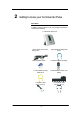
2 Getting to know your Commander Pulse Parts Check In addition to this document on CD, your package should arrive containing the following: 1 Commander Pulse Unit 1 Power Supply Commander Pulse (PSU) 1 Documentation Pack 1 Blue (Ethernet WAN) cable RJ-45 1 Cordless handset & charger 1 Yellow (Ethernet LAN) cable RJ-45 1 Main distributor frame cover (MDF) 1 Gray line cable (RJ-11 to RJ11) 1 Violet ADSL cable (RJ-11 to RJ-11) 9
Front Panel The front panel contains a ‘Page’ button and lights called Light Emitting Diodes (LEDs) that indicate the status of the Commander Pulse. Pressing the ‘Page’ button rings all the cordless handsets registered to the Commander Pulse.
3 Connecting Your Commander Pulse These instructions are a guide to the installation and basic configuration of the Commander Pulse. Step 1: Siting your Commander Pulse Unit Environment The Commander Pulse must be located in dry area and not exposed to excessive levels of heat, dust, damp or high humidity.
Wireless LAN range The line of sight range between the Wireless LAN transmitter and a wireless PC is 30m. This range is achieved in a perfect environment with nothing between the Commander Pulse and the PC. This range is reduced when used indoors by the factors mentioned above. Keystations location The keystations have a 3m cord. This means that the keystations can be up to 3 meters from the Commander Pulse before additional telecommunications cabling is required.
Fit the Cable Cover over the phone connections. Locate the lower pins first Step 3 Internet Access Connections Connecting to an ADSL Line If you are connecting to the Internet via another modem (e.g. iBurst, Cable modem etc) please proceed to “Connecting to an External Modem” below. If you are connecting to the Internet directly over an ADSL line both the ADSL line and the PSTN Line provided with the ADSL service should now be connected to the Commander Pulse.
Connecting to an external modem I f you are connecting to the Internet via another modem (e.g. iBurst, Cable modem etc) connect the Blue cable provided to the Blue WAN connector on the back of the Commander Pulse. Connect the other end of the blue cable to the LAN port on the external modem. Step 4 Connect the Power Power up the unit by connecting the AC power adapter to the Commander Pulse, connect the adapter to the power point and turn on the power point.
5. Press the Scroll Down Key (Ô) until ’Equipped lines’ is displayed. 6. Select ’Line 2’. The symbol beside line 2 changes from “♦” to “◊“ indicating the line is not equipped. Note If you do not have a keystation see the “PABX Configuration using the web interface” section in the Owner’s manual for instructions on programming the number of equipped lines Step 5 DECT Phones Assemble your DECT Phone Place the 2 rechargeable NiMH batteries size AAA 1.
Note Pressing the “Page” button normally (for less than 2 seconds) rings all DECT phones registered to the Commander Pulse. This can be used to locate misplaced DECT phones. Safety precautions: Do not allow the DECT handset to come into contact with liquids or moisture. Do not allow the charging contacts or the battery to come into contact with conductive materials. Do not use the handset in an explosive hazard area such as where there is gas leaking.
a. Connect the yellow LAN cable to the LAN connector on your PC. b. Connect the other end of the yellow cable to the Commander Pulse. c. Turn on your PC and open your web browser, (e.g. Internet Explorer) d. Type in the web address of http://192.168.1.1 into your web browsers address line and press enter. Continue with programming as described on Page 23 Cabling Keystations & Standard telephones Pulse keystations & Standard telephones can be connected directly to the system using the telephone cord.
Wall Mounting the Commander Pulse The Commander Pulse can be wall mounted. You can print this page and use it as a template for locating the wall mounting screws supplied 150.
Keystation connections (underside of phone) Handset connector [B1] Line cord connector Data Port Headset Port Plinth 19
Attaching the keystation desk plinth The desk plinth allows you to mount the keystation at two angles. Wall mount Plinth position Plinth position 35° Plinth position 20 ° Wall-mounting a keystation The phone plinth is inverted on the base to wall mount the phone. Locate, drill and plug the 2 screw locations as shown below. The holes should be deep enough to accept a 2.5 cm screw. Insert the two screws leaving sufficient space to clip the base over them. Locate the phone and base over the screws.
Wall hook when the keystation is in a 20 degrees or 35 degrees position Wall hook when the keystation is wall mounted.
Door station The door station is connected to station 23. Door Station bracket Mounting screw Connect the single pair from the door station to the AB connections on station 23. Cabling must be installed by a qualified ACMA cabler. WARNING The system must be programmed to recognize the door station See page 172 for programming via a keystation and page 100 for configuration via the Web Management application. Power Fail Telephone Connect a standard analogue telephone to the Power Fail connector.
4 Basic programming using the Management Application The Commander Pulse includes a series of Web management pages that provide an interface to the software installed on the Commander Pulse. It enables you to configure the Commander Pulse. By accessing the Management application through your web browser from any PC connected to the Commander Pulse via the wired or wireless LAN. Note By default the Wireless network card in the Commander Pulse is disabled.
Note If you receive an error message or the Welcome page is not displayed, see Configuring your PCs on page 202. This is the first page displayed each time you log in to the Web It provides links to the programming pages that are most commonly used. This page contains links to the following pages: • Basic PABX Settings. (The most common settings for the telephone system). • Username / Password.
• Station Class of Service. Restricting phones from making particular types of call e.g. International calls • Cordless phone Registration. The cordless phones must be registered on the system before they can be used to make telephone calls • Line Divert. On Power up incoming calls are forwarded to the Answering Machine if they are not answered within 18 seconds. The forwarding set for each line can be changed or cancelled Incoming Ringing You can determine which phones ring for incoming calls.
Station Names The settings on this page have an effect on an station by station basis. Individual features can be set or unset for particular stations on the system. You may assign names to stations. When an station receives an internal call, its 'display' will show the calling station name in the place of the calling station number. To set the station name, left mouse click on the field and enter the name associated with the station. A maximum of 10 characters per name can be entered.
Station Class of Service The Class of Service feature allows the user to define barring settings for each station connected to the system restricting that station from making certain types of calls from the system. The following restrictions can be defined on a per station basis: • No Restrictions WARNING • Restrict International • Local Only • Emergency Calls Only • By default ALL stations can dial ALL destinations.
Programming Class of Service Codes The definition of what constitutes Restricted, Allowed, National & International calls, is determined by the leading digits of the dialed number. Thus, for example, numbers beginning with ‘0011xx’ are International calls. Numbers beginning one ‘1xx’ are local calls. The definition of Allowed and Restricted codes is at the user’s discretion. 50 entries can be configured in the dialing codes for International, National, Allowed & Restricted numbers.
DECT handset Registration The DECT Handsets are shown as registered or not registered. When “Register a handset” is selected a prompt is displayed indicating that the ‘REG’ key on the cordless phone should be selected and that the PIN is 1234. The system is set in registration mode for 30 seconds To unregister a DECT station, select “Unregister”.
Basic Router Configuration for an ADSL connection Username / Password The default settings for Internet Access over an ADSL line are set so that the only settings that must be entered to access the Internet are the Username and Password as supplied with your ADSL service. In some cases the User Name only is supplied. In this case you enter the User Name only. When User Name / Password is selected on the Welcome page the following page is displayed: 1.
Basic Router Configuration for a Cable Modem connection If your Internet access is provided by a cable modem the following programming is needed 1. Select Router Configuration from the main menu. 2. Select WAN/DMZ Port from the sub-menu. The following screen is displayed: Select the Change the WAN/DMZ settings here. The following screen is displayed: Select IP Gateway and Next. The following screen is displayed. Two options are presented. DHCP - automatically assigns IP addresses.
Select Confirm Changes. The setup is now complete. If you have been supplied with a number of IP addresses the Static option should be selected. See the detailed description on page 88.
Date & Time Settings Use this screen to program Time and Date settings for your system. Date Use this field to enter the system Date - the time is in the DDMMYY format, DD is the day, MM is the month, & YY is the year. For example, 3rd May 2006 =030506 Time Use this field to enter the system time - the time is in the 24hour clock format.
5 Using Your Commander Pulse Phone System System Description • The Commander Pulse is an Integrated Communications System supporting all your voice & data needs. • The Commander Pulse can accommodate 2 PSTN lines. • The Commander Pulse system can accommodate 4 wired keystations / Standard phones, as well as 6 cordless sets. • The Commander Pulse keystation has a simple-to-use menu-driven interface. • A door station is available that can be programmed to ring any station.
Getting Started This section of your Owner’s Manual is your guide to using the Commander Pulse system and its features, with either a keystation or a standard telephone. It also explains how to program system settings using your keystation. Read the section ‘System Keystation’ on Page 36 to understand how to operate the menus and use the other features of your keystation. To get up and running with your keystation, read the section ‘Getting Started – Basic Call Features ’ on page 46.
System Keystation Introduction to your system keystation The system keystations are highly featured display telephones for use with your Commander Pulse system. It features a 4-line display that contains prompts and menus with selectable options. This unique menu-driven interface makes the system simple to use, and no codes are needed to program and activate features. The keystation is also equipped with a data port, positioned on the lefthand side of the phone.
Menus When the keystation is idle, the Idle Menu is presented containing a large number of options displayed in groups of three. This menu, showing the first three options, is shown below. (Use Scroll Keys below display to scroll up and down). If you are on a call or operating a feature, the menu changes to offer only those options relevant to what you are doing. Also, when features such as Station Lock are set, the first prompt on the display becomes the option to cancel the activated feature.
Using the Keypad The Keypad can be used to enter digits when dialing or text when programming names or messages. How to enter text when programming names or messages Press 2 once for A, twice for B, and so on. (Pressing 2 continuously loops through ABCabc2). Press 3 once for D, twice for E, three times for F, and so on. Selecting a different key moves the cursor on automatically to the next location.
Using the Volume Key To adjust the speaker volume, press the Volume Key when in Hands-free Mode. To adjust the handset receiver volume, press the Volume Key when in Handset Mode. To adjust the ringing volume, press the Volume Key when the keystation is ringing. Note The Volume level increases/decreases by one step for every press of the Volume Key. Using the Mute Key The Mute Key can be pressed when you are using the handset or in Hands-free Mode.
3. Select ‘Key programming’. 4. Press the Programmable Key to be programmed. A list of options appears on the display. 5. Select the required feature to be programmed onto the key. Use the Scroll Down Key (Ô) to scroll down to view the list of available features. For example, to program the key with a speed dial number, select the ‘Individual digits’ option 6. Press the Hands-free Key to finish programming.
To enter system programming If your station is the Programming Station you have access to the system programming options. If you select this option you will be prompted to enter the System Programming Password. If this option is selected from any other station the display will show ‘Programming Refused’. Again, the default Programming station is station 20. 1. From the Programming Station, press the PROGRAM Key 2. Press the Scroll Down Key (Ô) until ‘System programming’ is displayed. 3.
Using the DECT Handset The DECT Handset is designed for use with the Commander Pulse. The keys are as shown. For a detailed description of the functionality see Appendix A on page 181.
Making a call Press Dial the number you want to call. The number appears on the display and is dialed. Note Note Note Call timer: The call timer shows the duration of your current call on display. Out of range warning: If you move too far away from the base Commander Pulse during a call, your phone will sound an alert tone, and will flash. You need to move closer to the base Commander Pulse or your call will be disconnected.
Redial a number Your phone records the last 10 numbers you have dialed. The most recent call is stored at the top of the list. Only the first 20 digits of each number are stored. To redial the last number dialed: 1. Press . 2. Press REDIAL. The last dialed number appears on the display and is dialed. 3. To redial one of the last 10 dialed numbers: 4. Press during standby. The redial list appears on the display. 5. Press to select the number you wish to redial. Press.
Message Waiting Indication A message indication symbol appears on your DECT handset and a broken dial tone is heard when going off hook, when a message has been left in the Answering Machine or the station’s voicemail. To access the message press and dial *. To access the answering machine dial 9 as the station number. The default password is 1111 for all mailboxes. Note It is recommended that all mail boxes passwords are changed from the default password for security.
Keystation – Basic Call Features Making and Answering Calls Making an external call. There are two basic modes of operation available for making external calls. In the normal mode, which is the default, a line access digit (0) is dialed to select a Line. If Automatic Line selection (ALS) is programmed you do not enter ‘0’ the line access code. Making an external call in normal mode - - Press a Line Key to select a free line and when dial tone is returned dial the external number.
Speed Dial list Each station can program up to 30 Individual Speed Dial numbers. You can also program 99 System speed dial numbers and names. Users of the system can access the system speed dial numbers, provided they are not restricted from dialing the number because of their Class of Service. An option is available where stations can dial numbers in the system speed dial list even though they are normally restricted from dialing them. See System Speed dial override programming on page 105 and page 166.
To dial a System Speed Dial number 1. Press the DIRECTORY Key. 2. Select ‘System speed dial’. 3. Enter the first letter of the name or scroll through the entries to find the entry you want. 4. When you have selected the number or name you want a free line is automatically selected and the number is then dialed. If some numbers are entered without names they are presented at the end of the list. To answer a call When the keystation rings, you can do one of the following: 1.
To transfer a call to an external number 1. While on the call, press the Scroll Down Key (Ô) until ‘External transfer’ is displayed. 2. Select ‘External transfer’. 3. Select a free line and dial the number. 4. When the call is answered, press ‘Transfer’. Note Transferring an external call to an external number ties up two exchange lines. Such calls are called trunk-to-trunk calls.
5. Forward will be ignored for internal calls. For internal calls the phone will ring (only If External forwarding is set to the 'External calls only' option). 6. If your station is allocated a voice box select 'Divert to Voice Mail' 7. Select ‘Confirm’ (Only appears if destination is an external number). WARNING It is possible that an station may misuse the External Divert facility. The default setting is that no station is allowed to set the facility.
3. Select ‘Confirm’ to accept the number. To set a 'Divert when Busy' from a standard phone the code is '733' followed by the destination number. WARNING Note It is possible that an station may misuse the External Divert facility. The default setting is that no station is allowed to set the facility. When ‘Forward when busy’ is enabled on an station to Forward to an external number, external incoming calls will divert but internal calls will not.
Line Divert This feature allows any station to set a divert for an exchange line. Setting line forwarding from a system phone 1. From the Idle Menu, press the Scroll Down Key (Ô) until ‘Line Divert is displayed 2. Select the line. (The station may be programmed for more than one line) 3. Select the Option required 4. Enter the destination number. 5. Select ‘Answering Machine’ to forward the calls to the answering machine. It is possible that an station may misuse the external divert facility.
Using your keystation with a headset Your keystation is equipped with a socket for a Headset. Plug a headset into the socket. 1. From your keystation, press the PROGRAM Key 2. Select ‘Headset Mode’ and select ‘Turn Headset On’. The phone is now programmed to operate with a headset. 3. 'Turn Headset Off?' is now displayed to allow you to revert to handset mode. 4. If ‘Turn Headset Off?’ Is selected the menu updates to show ‘Turn Headset On?’ You can turn the headset on and off as required.
Using a Standard or DECT Handset Feature Access Code List You may access the range of Commander Pulse features with a standard or DECT Handset. To use a feature, dial the appropriate code from the list below. If your telephone is equipped with memory keys you may program feature codes onto the keys - refer to your telephone user guide for instructions. On the cordless phone you can program codes under the Services (SER) key. See Page 187.
Making External Calls There are two modes of operation available for making external calls. The normal mode, which is the default, a line access digit is dialed to select a external line. If Automatic Line selection is programmed you do not enter the line access code. To make an external call in normal mode 1. Lift the handset, or use a Hands-free Key, if available on your telephone. 2. Obtain a free line in one of the following ways: 3. Dial 0 to get an outside line 4. Dial the number you require.
To make an external consultation call While on an external call you can contact another station to make an enquiry, as follows: 1. While on an external call, press the Recall Key on your telephone. 2. Dial the station number. 3. To return to the external call and place the station on hold, press Recall and dial 2. 4. To return to the external call and release the station, press Recall and wait or press Recall and dial 1.
Line Divert Divert all calls 1. Lift handset or use hands-free if available. 2. Dial 792 followed by the line number (1-4) 3. Dial the station number, or 4. Dial the external phone number (including line access code 0) 5. Followed by #. Cancel Line Divert all calls 1. Lift handset or use hands-free if available. 2. Dial 792 followed by the line number (1-4). Divert calls when line is busy 1. Lift handset or use hands-free if available 2. Dial 793 followed by the line number (1-4) 3.
Programming and dialing speed dial numbers If you have a standard telephone, you can program up to 10 Personal Speed Dial numbers. To program a Personal Speed Dial number 1. Lift the handset, or press the Hands-free Key, if available. 2. Dial the code 75. 3. Enter the location (01 - 30) where you want to store the number. 4. Dial the number you want to store. 5. Go on-hook. The line access codes 'e.g. 0' is not required Note To dial a Personal Speed Dial number 1.
Call Pick-up This feature allows the user to pick up any call, ringing at another station. These calls include: - Internal calls - External calls - CLI Routed calls - Incoming ringing calls routed to a single station To pick up a call ringing at another station - From the Idle Menu, select the ‘Call Pick-Up’ option on the display. - From a standard telephone, the code is 727.
To present a busy station with a Call Waiting tone Select ‘Waiting tone’ on the display when a busy tone is returned from a station. From a standard telephone, the code is Recall 8. To accept a waiting call If another station presents you with Call Waiting, this will be indicated on your display and you will hear the Call Waiting tone, provided your station is not protected against Call Waiting tones. Select one of the options presented on the display.
When a new record is received and the memory is full the oldest record is discarded from memory. The CND list can be allocated as one central store of data on calls received. This store alerts station 20 (default), by means of a display prompt, that new calls have been stored. You can also program all keystations to store up to ten numbers each. To examine and redial stored caller numbers Select ‘Call Log - Personal’ to examine the numbers in the personal store of your keystation.
Paging To make an announcement over the speakers of all keystations The 'Page All Keystations’ allows any station to make an announcement over the speakers of all keystations. Only keystations that are pageprotected will not be paged. - From the Idle Menu, press the Scroll Down Key (Ô) until ‘Page all Keystations’ is displayed. - Select ‘Page all Keystations’. Make your announcement. From a standard telephone, the code is 795.
Sending a Forward Recall while on call A Forward Recall signal may be required if you are using certain network services on your PSTN lines, or if your Commander Pulse is connected to another telephone system (PABX) via one of the line interfaces. The Forward Recall feature allows you to send a hold signal forward on the line to the exchange or PABX. To send a hold signal, you must be on a call or have dialed at least one digit of the number you are calling.
Station Set-Up options Do Not Disturb If your station is set to ‘Do Not Disturb’, anyone trying to call you will receive a busy (engaged) tone. If the person trying to contact you has a keystation, ‘Do Not Disturb Enabled’ will appear on its display. ‘Call Back’ and ‘Alarm call’ are the only incoming ringing that will be accepted when this feature is set. To set Do Not Disturb on your station 1. From the Idle Menu, press the Scroll Down Key (Ô) until ‘Do Not Disturb’ is displayed. 2.
To change your station Lock Password 1. From the Idle Menu, press the Scroll Down Key (Ô) until ‘Station Lock’ is displayed. 2. Select ‘Station Lock’. 3. Select ‘Change the lock code’. 4. Dial the existing 3-digit Lock Password. The default password is 123. 5. Dial your new 3-digit Lock Password. The new Lock Password will not be displayed when entered. Press the Hands-free Key to finish programming. From a standard telephone, the code is 714.
Incoming Call Handling General Incoming Calls can be programmed to ring any number of stations. For configuration via the web interface, see page 98. For configuration via the keystation interface, see page 160. When calls are received on a line all free programmed stations are rung. If the call is not answered it is forwarded to the Answering Machine after the forward on no answer timer expires. Note The divert on no answer timer is set at 18 seconds in default. This timer can be changed.
Hotline Stations can be programmed so that they automatically dial a number when they go off-hook. The number dialed can be an station or an external number. For configuration via the web interface, see page 103. For configuration via the keystation interface, see page 163. Assigning Station Names You may assign names to stations. When an station receives an internal call, its display will show the calling station name in the place of the calling station number.
3. Enter your Voicemail Password, which is 1111 by default, followed by #. 4. Select ‘Play’. The new messages are played. Note Each message is time stamped to tell you when the message was received. When all new messages are played, you are informed of the total number of messages in your voicemail box. You may skip the time stamp by dialing 8, which jumps forward ten seconds. Forward a message from a keystation A user can forward a message from their voice box to another voice box.
Transferring calls to Voicemail Boxes You can transfer calls to any Voicemail Box without calling the station. When you are on a call select 'Transfer to Voice Mail' 1. The menu is updated showing those stations equipped with voicemail boxes. 2. Select the station from the menu 3. Select ‘Transfer’ or replace the handset. For standard telephones the user should press the recall key and dial 710 followed by the station number. Replace the handset.
- Dial 5 Go back to the previous message - Dial 7 Go back ten seconds - Dial 8 Go forward ten seconds / Skip the time stamp - Dial 9 Forward the message to another station - Dial 0 Return Call. Automatically make a call to the caller who left the message (this feature is not applicable when mailbox is accessed remotely). To monitor/pick-up callers as they speak to your Voice Mailbox You can operate your voicemail in Voicemail Monitor Mode.
When a user turns remote notification on, a call will be made to an external number programmed by the user to notify them that they have received a new voicemail message in their voicemail box. The user can set up remote notification to notify them of all new messages or only those marked as priority by callers to their voice mail. Remote notification can be turned on and off as required.
To operate voicemail from a standard telephone Standard telephones can also be allocated Voice Mailboxes. When a Voice box is allocated the ‘Forward On No Answer’ is automatically set for the station. You can set ‘Forward All Calls’ or ‘Forward when busy’ to the Mailbox as well by setting the Forward to 710.
Answering Machine In default all calls received are Diverted on No Answer to the Answering Machine. This additional feature allows you to set up the Answering Machine so that it can be turned on and off as required. You can also set the timer so that the answering machine answers calls immediately or after ringing for a period You can select which lines are to be answered by the answering machine when it is turned on.
To change the greeting on the Answering machine 1. Press the MESSAGE Key. 2. Select “Answering machine” or dial 9 as the station number 3. Enter your Voicemail Password, (1111 by default), followed by #. 4. You are presented with the Voice Messaging Control Menu. The options displayed are ‘Play’, ‘Erase all messages’, ‘Greeting’, ‘Change Password’, ‘Monitor’ and ‘Cancel’. 5. Select ‘Greeting’. 6. Select ‘Record greeting’ 7. Speak to record a personalized greeting when prompted. 8.
External Diverting Options This allows you to decide if external callers or external and internal callers to your station are forwarded externally. It also allows stations to be prohibited from activating an external forwarding. - Note For configuration via the web interface, see page 104. The Divert on no answer timer is set at 18 seconds in default. This timer can be changed.
6 Connecting to the Internet If your Internet Service is provided over an ADSL line you must configure the ADSL modem as described below. If your Internet Service is provided by a Cable Modem you must configure the unit as an IP gateway. Go to page 87 for the details on configuring an IP Gateway. ADSL Modem configuration The Commander Pulse is configured with basic settings that will suit most ADSL connections.
If your ISP wants you to connect to the Internet using PPPoA, follow the instructions below. 1. From the left-hand Setup menu, click on Router Configuration. The following page is displayed: 2. Click on ADSL Modem. The following page is displayed: This page displays information about your current Internet access configuration. 3. Select Change the ADSL Modem settings here.
4. Select PPPoA and Click Next>. The following page is displayed: 5. Enter the PPP username and password provided by your ISP. Type them in the relevant boxes, 6. Click Next>. The following page is displayed: The settings of VPI=8 and VCI=35 are the default settings. If your ISP has supplied you with different values enter them here. 7. Click Next>. The following page is displayed: This page confirms your PPPoA settings. 8. If you are happy with your settings, click Confirm Changes.
If your ISP wants you to connect to the Internet using PPPoA, follow the instructions below. 1. From the left-hand Setup menu, click on “Router Configuration”. The following page is displayed: 2. Click on “ADSL Modem”. The following page is displayed: This page displays information about your current Internet access configuration. 3. Select Change the ADSL Modem settings here. The following page is displayed 4. Select PPPoE and Click Next>. The following page is displayed: 5.
6. Click “Next>”. The following page is displayed: The settings of VPI=8 and VCI=35 are the default settings. If your ISP has supplied you with different values enter them here. 7. Click “Next>”. The following page is displayed: This page confirms your PPPoE settings. 8. If you are happy with your settings, click “Confirm Changes”. The Internet Access page is displayed.
Enabling MAC spoofing Note You should only enable MAC spoofing if your ISP has requested that you do so. In most cases, you will not need to do this. Your ISP identifies your modem by its unique hardware number or Media Access Control (MAC) address. If you are using PPPoE Internet access, your ISP may want you to spoof the identity of a different device. You can spoof the MAC address of another device by replacing your Commander Pulse’s existing MAC address with another device’s address.
Configuring a DHCP ADSL connection – RFC 1483 If your ISP uses a DHCP DSL connection, your ISP may tell you to set unique path and circuit numbers (called VPI and VCI) in order to connect your Commander Pulse to the ISP’s Internet service. In most cases, your Commander Pulse will use default settings, so you may not need to enter these values. Note Your ISP will provide you with the VPI/VCI values necessary to setup a DHCP DSL connection. 1. From the “ADSL Modem”: Types of Access page select “DHCP” , 2.
5. Select “Next”. The following page is displayed: The settings are shown. If you are happy with them press “Confirm Changes”.
3. Click in each box and type the relevant address information provided by your ISP. 4. Click “Next>”. The following page is displayed: 5. Select the Option provided by your ISP. The following page is displayed: - 6. Enter the VPI and VCI values supplied by your ISP 7. Click “Next>”. The following page is displayed: - This page confirms the address settings that you have manually configured (the values displayed above are for example purposes only).
Changing the ADSL Modem Operating Mode The ADSL modem is configured to operate in ADSL2+ mode and will normally connect to the ADSL line using the appropriate mode for the line. There may be cases where it is necessary to change the operation mode manually. 1. On the ADSL modem page shown above select ‘Change the ADSL Modem operating mode’ 2. Select the appropriate Operating Mode. The information on the appropriate mode is available from your ISP.
Connecting to an External ADSL Modem, Cable Modem, LAN, WAN or add a host to the DMZ The WAN/DMZ port can be used to connect to an external ADSL modem, a LAN or a WAN, or to add a host to the DMZ. 1. 2. Select Router Configuration from the main menu Select WAN/DMZ Port from the sub-menu. The following screen is displayed: 3. Select the Change the WAN/DMZ settings here. The following screen is displayed Three options are presented. - PPPoE - IP Gateway - DMZ.
1. Select “PPPoE”. Click Next. The following screen is displayed 2. Enter a Username and Password. Retype the Password. Select Next. The following screen is displayed 3. Select Confirm Changes. The following screen is displayed The PPPoE setup is now complete IP Gateway to connect to Cable Modem, LAN or WAN IP Gateway is typically used when connecting to a Cable Modem LAN or WAN. Select IP Gateway. Select Next.
DHCP This is described in detail earlier in this manual. For details see Page 31. Static 1. Select “Static”. 2. Click Next. The following screen is displayed. 3. Enter the IP addresses and Subnet mask. Click Next. The following screen is displayed. 4. Select Confirm Changes. The following screen is displayed: The Static IP Gateway setup is now complete.
DMZ A host can be connected to the WAN/DMZ Port. In default the Wan/DMZ port is configured as a DMZ. On the Router configuration page select WAN/DMZ Port. The following page is displayed: 1. Select Change the DMZ IP address here. The following page is displayed: 2. Enter the host IP address and subnet mask. Click Next. The following screen is displayed 3. Select Confirm Changes. The following screen is displayed The DMZ setup is now complete.
Password You can restrict access to your Commander Pulse’s web pages using password protection. With password protection enabled, users must enter a username and password before gaining access to the web pages. By default, password protection is enabled on your Commander Pulse, and the username and password set are as follows: Username: admin Password: admin For more information, see Accessing the Web pages on page 23.
This page displays the current username and password settings. Type your own unique username and password in the relevant boxes. They can be any combination of letters or numbers with a maximum of 20 characters. The default setting uses admin for both the username and password. We recommend that you do not set the same character combination for both username and password 3. Click Next>.
DHCP Server A DHCP (Dynamic Host Configuration Protocol) Server is a system that assigns IP addresses to the multiple stations on the network. Dynamic Host Configuration Protocol is a scheme where a client host "leases" an IP address. This can be great on a largescale network because it assigns an IP address, and many other options, such as DNS servers, WINS Servers, and other options. 1. Select Router Configuration from the main menu. 2. Select DHCP Server from the sub-menu.
Parameters for this subnet The current subnet parameters are shown. These can be changed if required. IP addresses to be available on this subnet The range of IP addresses available on the subnet is shown. These can be changed if required. DNS Server option information The default setting is use local host as the DNS server - all DNS requests are sent to the default gateway 192.168.1.1 which then relays the request to the DNS addresses negotiated at start up. Specific DNS servers can be defined if required.
The following screen is displayed Select on of the following options from the drop down menu: Select the option required from the drop down menu. - Default gateway - Domain name - IRC server - HTTP server - SMTP server - POP3 server - NNTP server - WINS server Time server Enter the option value in the field below. Select OK To create a new subnet 1. Select Create new subnet. The screen displayed is the same as Edit DHCP server subnet with the Additional option information option.
Enter the maximum lease time in seconds Select “OK”. Addressing The Addressing page displays information about your LAN IP address and allows you to change the address and subnet mask assigned to your Commander Pulse. Note You should only change the addressing details if your ISP asks you to, or if you are familiar with network configuration. In most cases, you will not need to make any changes to this configuration.
Note 2. Click Next>. The following page is displayed: 3. This page displays the new IP address and subnet mask and asks you to confirm whether these are correct. Click Confirm Changes. The Addressing page is displayed, confirming your new LAN address settings. If you change the LAN IP address of the Commander Pulse while connected through your Web browser, you will be disconnected. You must open a new connection by entering your new LAN IP address as the URL. See Accessing the Web pages on page 23.
7 PABX Configuration using the web interface Your PABX (Phone System) can be completely configured via the web management system. The web management Welcome page contain a link to Basic PABX Settings, which are the configuration options that the user will most likely wish to change. The Basic PABX Settings are: - Incoming Ringing - Station Names - Outgoing Restriction - Station Class of Service - Cordless Registration - Line Forwarding Instruction for setting these basic options are given below.
Incoming Ringing By associating lines with individual stations, you can have lines ringing different stations in Day and Night modes. For example, in DAY mode, all calls on line1 might ring all phones, but in NIGHT mode all calls on line 1 might be set to only ring station 20. Also, in both DAY & NIGHT modes, all calls on IP Trunk (VoIP) might be set to ring on station 23 only. To change the settings, select ON or OFF from the relevant drop down box for the Line/Station configuration you require.
System Settings Use this screen to program system wide settings for your system. Activate Night Service This feature allows the user to activate night service (normally out-of-hours working). Night service set-up is used to define which station rings on incoming calls, what the Class of Service is for each station and what type of voice greeting is played. The system operates in DAY MODE unless the night service option is specifically programmed to operate.
Answering Machine Password The password can be between 1 and 8 digits long and can be any number between 1 and 99999999 This is the password used to access the system answering machine from station 20.
Automatic Line selection When Automatic Line selection is turned on when an station goes off hook and dials a free line is selected and the digits are sent to line. Internal calls are made by selecting the internal call menu on keystations or by pressing Forward Recall and dialing the station number. System Speed Dials You can dial your System speed dials from the relevant option on your keystation menu or by dialing the appropriate short code access from any analog phone.
Uploading System Speed Dials list Alternatively, you may upload the System Speed Dials from a .CSV (spreadsheet) file. To do this, click Upload on the Edit System Speed Dials page and follow the instructions. The file must be in .CSV format, with names in the first column, and phone numbers in the second column. You can export files in this format using typical spreadsheet software, e.g. Microsoft Excel Station Settings The settings on this page have an effect on an station by station basis.
Advanced Options Select this option to edit Advanced Options for individual stations. Note Advanced Options for the cordless stations contain only a subset of the below features, as some of the features are not relevant for cordless stations. Disconnect Use this option to functionally disconnected the station from the system (this option does not physically disconnect the station). Page Protection When selected the station in question will not receive pages from keystation ‘Page-all’ calls.
Left mouse click on the field and enter the hotline number associated with the station. This is a telephone number up to 24 digits in length. The user can enter another station number, or an external number as required (include 9 to seize the outside line). Not Allowed to Open the Door The selected station cannot be used to open the door when a call is placed over the door station. Forward All Before you leave your station, you can Forward all your calls to ring at another station.
WARNING It is possible that a station may misuse the External Forward facility. The Default setting is that no station is allowed to set the facility. Broken tone will be heard at your station until all call forwarding is cancelled. Note You cannot Forward to a station that has the ‘Do Not Disturb’ feature set. Do Not Disturb If your station is set to ‘Do Not Disturb’, anyone trying to call you will receive a busy (engaged) tone.
Personal Speed Dials You can dial your personal speed dials from the relevant option on your keystation menu or by dialing the appropriate short code access from your analog phone. This page allows the user to enter up to 30 personal speed dial numbers for each station. The personal speed dials are referred to as Index 1 – 30. You may also associate a Name with each Speed Dial entry. Name Enter up to 10 characters in this field Number Enter up to 20 digits in this field.
Program Keys This option applies to keystations only. There are 8 programmable Function Keys on your system keystation. In default mode, the keystation ‘Program Keys’ are programmed to select the external lines available on the system, the first key for Line 1 the second for Line 2 and so on. Using your mouse left click on the ‘Function’ menu option next to the Key you wish to program. From the drop down list available, select the required setting.
Line Settings The settings on this page have an effect on a line by line basis. Individual features can be Enabled or Disabled for particular lines that are connected to the system. Equipped The system assumes that available line interfaces have external lines connected to them. If a line interface does not have an exchange line connected, ensure correct system operation by unequipping the line interface in system programming Select this option to enable/disable lines connected to the system.
Advanced Options Dial Tone Detect This option requires the system to detect dial tone before calls can be made. If set to Off, this feature prevents the system from dropping the line when dial tone has not been detected. In this case, the line is released if no digit is dialed until the expiration of a timer.
For each incoming line (Line 1 and 2, IP Trunk 1 & 2) you can define what number to forward the call to for the cases of No Reply, Busy & All Calls. (See also PABX Configuration -> Station Settings -> Advanced Options) Class of Service The Class of Service feature allows the user to define restriction settings for each station connected to the system prohibiting the station from making certain types of call. The following restrictions can be defined per station: - No Restrictions i.e.
Similarly if you want restrict particular numbers enter them in the Restricted Codes list and set the Restricted Codes to on for the station. Note If 'Emergency Only' is set, Allowed and Restricted codes have no effect. Day and Night Mode There are different settings for Day Mode and Night Mode. To configure Day/Night mode see PABX Configuration -> System Settings.
Timers The timers listed below are under the control of the user and therefore can be changed from the default setting, provided the new settings is within the individual timers limits. Recall On Hold This is the time that elapses before a call, which has been placed on hold, rings back the station that put the call on hold. Recall On Transfer This is the time that elapses before a call, which has been transferred and not answered, rings back the station that attempted the transfer.
Answering Machine This is the time that elapses before an unanswered incoming call is presented with the System voice mailbox greeting. Voice Mail Message Length This is the maximum length of a message left in a Mailbox or a Greeting for a Mailbox, Auto Attendant or Courtesy service. Remote Notification Delay This is the delay between receiving a message in a voice mailbox and setting up the remote notification call.
Edit LCR Codes Using this page you may define the Least Cost Routing criteria. Up to 50 LCR rules may be defined (Index 1 – 50). In the ‘Input Code’ field you insert the relevant dialed digits (e.g. ‘0011’ for International calls or ‘0011’ for International calls to the USA). In the Output Code field, you insert whatever digits you want to be passed to the network. If no additional carrier access codes are required, then the Output Code is the same as the Input Code.
CLI Routes Using this feature, incoming calls from particular numbers can be associated with a particular name and routed to a predefined station. In the number field, enter the callers number (CLI) as is delivered by the network. You may choose to associate a name with this number. Select the station to be rung when this number is detected.. Options for Day & Night routing exist. To set the system Day & Night mode times see PABX Configuration -> System Settings.
Outgoing Restriction Use can use this feature to restrict a station from being able to make outgoing (external) calls on particular lines Configure the restriction for each line separately, i.e. Turn OFF for those stations that are not allowed to select the particular line to make outgoing calls. Remote Notification The various settings for remote notification of voice mail messages are set here. Set ‘Allowed’ on for those stations allowed to activate remote notification.
Enter the personal number if remote notification is to a telephone number Enter the Pager Company number and the Pager dial string if notification is to a pager company Also three delays are provided between the call to the Pager Company being answered and the pager string being dialed. This is set at a short delay. There are a number of systemwide settings which cannot be set by individual stations.
8 Advanced Router Settings Wireless Setup / Security This chapter assumes PCs are already equipped with a wireless card. The Wireless Network page allows you to configure the Wireless features of your Commander Pulse. 1. From the left-hand Setup menu, click on Wireless Setup / Security. The following page is displayed: To enable the wireless network 2. Select Enable or disable the wireless network here... in the General Settings 3. Select Enable and Next.
The following page showing the Wireless Network name is displayed Your Commander Pulse and all of the wireless PCs in your wireless LAN share the same wireless network name. This name (commonly known as the Service Set Identifier (SSID)) distinguishes your Wireless network from any other(s) that may be in use nearby. It also ensures that only those PCs configured with the same name as the one set on your Commander Pulse can obtain access to it.
Select a suitable channel (as advised by your ISP) from the Channel drop-down list and then click Next>.
Configure Wireless Network Security The following page allows you to configure wireless security: You can protect your wireless data from potential eavesdroppers by encrypting wireless data transmissions. An eavesdropper might set up a compatible wireless adapter within range of your Commander Pulse and attempt to access your network. Data encryption is the translation of data into a form that cannot be easily understood by unauthorized users.
If you want to use WEP 64bit data encryption, click on the 64bit encryption on the wireless network radio button and then click Next>. Now follow the instructions in Configuring 64bit or 128bit encryption on page 123. If you want to use WEP 128bit data encryption, click on the 128bit encryption on the wireless network radio button and then click Next>. Now follow the instructions in Configuring 64bit or 128bit encryption on page 123.
Configuring 64bit or 128bit encryption The example set in this section is for 128bit encryption, however the outline also applies to 64bit encryption. 1. Once you have selected your WEP encryption method and then clicked Next>, the following page is displayed: 2. Click in the Key box and type a unique 26-character hex network key, such as A6F34B2CE5D68BE90A6F34B2CE. Note Hexadecimal or ‘hex’ numbers each have a value of 0 to 9 or A to F. Each number represents four bits of binary data.
Configuring WPA security Once you have selected WPA and then clicked Next>, the following page is displayed: 1. Type a unique pass phrase in the Pass phrase text box. Your pass phrase should be at least 20 characters long in order to deter potential intruders. 2. Once you have typed a pass phrase, click Next>. 3. If you are following the First Time Settings wizard, the next page in the wizard sequence is displayed, which allows you to Configure Wireless Address Authentication.
Configure Wireless Address Authentication The following page allows you to configure which wireless PCs can access the Commander Pulse: By default, any wireless PC that is configured with your network’s SSID and channel number can connect to your Commander Pulse. You may want to increase the security of your wireless network by creating one of the following lists of wireless PCs: A wireless PC blacklist; PCs on this list cannot access the Commander Pulse, but all other wireless PCs can.
Configuring the wireless PC blacklist 1. Once you have selected Allow all wireless PCs to connect except those I specify radio button and then clicked Next>, the following page is displayed: 2. To add a network PC to the blacklist, click Add an address here… The following page is displayed: 3. Click in each box and type each character pair of the MAC address for the PC you want to blacklist. Click Next>.
Configuring the wireless PC whitelist 1. Once you have selected Only allow the wireless PCs I specify to connect radio button and then clicked Next>, the following page is displayed: 2. To add a network PC to the whitelist, click Add an address here… The following page is displayed: 3. Click in each box and type each character pair of the MAC address for the PC you want to whitelist. Click Next>. The following page is displayed, containing details of the MAC address that you have just added: 4.
Confirm Wireless network changes Once you have configured Wireless Address Authentication and clicked on Next>, the following page is displayed: This page confirms the configuration changes made to each page in the wizard. If you are happy with these settings, click on the Confirm Changes button. Configuration changes are applied to the Commander Pulse and the Wireless Network page is displayed.
Setting the Country 1. From the First Time Settings section of the Wireless Network page, click Change your wireless first time settings here… The first page of the wizard is displayed: The number of valid wireless network frequencies varies from country to country and you need to identify which country you are operating the Commander Pulse in to ensure that your network will transmit on the correct frequency. The setting for the Australia is the default setting so you do not need to change it.
Click on the Confirm Changes> button to apply the configuration changes. Wireless Network General Settings The General Settings section of the Wireless Network page displays details of the Commander Pulse’s current wireless configuration. For example: The hyperlinks in this section allow you to: Enable/disable wireless networking; see page 118. Change the channel currently in use; click Change your wireless channel here… and follow the instructions in Select a Channel on page 124.
Displaying details of Wireless PCs At the Wireless Network page, click on View details of connected wireless PCs… The following page is displayed: This page displays the MAC address of the PC currently connected to your Commander Pulse, together with the signal strength. The signal strength is the measure of radio frequency (RF) energy detected by the Commander Pulse on a specific channel. Signal strength may vary depending on the position of the PC(s) in relation to the Commander Pulse.
From the left-hand Setup menu, click on Firewall. The following page is displayed: Select Firewall. The following screen is displayed The following screen is displayed Security State The Firewall is enabled by default Intrusion Detection is disabled by default. To disable the Firewall 1. Select “Disabled” 2. Select “Change State” 3. To enable Intrusion Detection 4. Select “Enabled” 5.
WAN <> LAN High Security Level Service Destination Port In WAN <> DMZ Out In DMZ <> LAN Out In Ou t Any Any HTTP DNS Telnet SMTP POP3 FTP ICMP SSH SIP TCP UDP TCP UDP TCP TCP TCP TCP N/A TCP UDP 0 -65535 0 - 65535 80 53 23 25 110 21 N/A 22 5060 6000 N N N N N N N N N N Y Medium Security Level Service Any Any HTTP DNS Telnet SMTP POP3 FTP ICMP SSH SIP 0 - 65535 0 - 65535 80 53 23 25 110 21 N/A 22 5060 - 6000 Any Any HTTP DNS Telnet SMTP POP3 FTP ICMP SSH SIP TCP UDP TCP UDP TCP TCP TCP TCP
To change the security level 1. Select the required level from the drop-down menu 2. Select “Change Level” NAT (Network Address Translation) NAT is enabled by default on the three interfaces. To disable NAT From the main Firewall page select the option required 3. Select “Disable NAT to … (Interface)” Restart the Commander Pulse for the change to take effect Global Address Pools A range of external IP addresses can be assigned to a specific interface. 1.
3. Select an interface from the drop down list 4. Enter an IP address and subnet mask, or enter the first and last IP addresses in the range 5. Select “Add Global Address Pool” Reserved Mappings Static routes can be defined between an external IP address and internal IP addresses. 1. Select “Advanced NAT Configuration …” 2. Select “Add Reserved Mapping … ” The following screen is displayed 3.
Policies, Triggers, Intrusion Detection, Logging The security policy settings, stateful inspection triggers, intrusion policy detection and logging settings can be displayed and changed. Security Policy This is used to add or delete filters 1. Select “Security Policy Configuration …” The following screen is displayed. 2.
Adding Port Filters 1. Select “Add TCP or UDP Filter” The following screen is displayed Enter the following parameters - IP Source address IP Destination address IP Protocol, TCP or UDP Source port or range of ports (associated with source IP address) Destination port or range of ports (associated with destination IP address) Direction, Inbound or Outbound 2. Select “Apply” 3. Save the new configuration 4.
- IP Protocol - Direction, Inbound or Outbound 3. Select “Apply” 4. Save the new configuration 5. Restart the Commander Pulse Host Validators Traffic to or from specific hosts can be blocked by the firewall. 1. Select “Host Validators …” for a particular interface The following screen is displayed 2. Select “Add Host Validator … ” for the selected interface The following screen is displayed 3. Enter the host IP address and Subnet mask 4. Select the direction, “Inbound”, “Outbound” or “Both” 5.
Application Level Gateways There are certain applications that NAT and Firewall configurations cannot manage. In many cases, ALGs (Application Level Gateways) are needed to translate and transport packets correctly. An ALG provides a service for a specific application such as FTP (File Transfer Protocol). Incoming packets are checked against existing NAT rules or Firewall filters, IP addresses are evaluated and detailed packet analysis is performed.
1. Select “Security Trigger Configuration …” The following screen is displayed Current security triggers are displayed. There is an option to delete each entry. 2. Select “New Trigger” The following screen is displayed 3.
Max Activity Interval The max interval time in milliseconds between the use of the secondary port sessions.
Use Blacklist Enables or disables blacklisting of an external host if the firewall has detected an intrusion from that host. Access is denied to that host for 10 minutes. Use Victim Protection Enables or disables the blocking of incoming broadcast Ping commands for the period specified in Victim Protection Block duration. Victim Protection Block Duration The period for which incoming broadcast Pings are blocked. The default setting is 600 seconds.
Security Logging 1. Select “Configure Security Logging …” The following page is displayed Logging is enabled by default for Session Logging, Blocking Logging and Intrusion Logging. To disable all logging: 1. Select “Disable Security Logging” Session Logging, Blocking Logging and Intrusion Logging. To disable any of the above 1. Select “Disable” 2.
Diagnostics A range of tests is available which can help in diagnosing problems. Select Diagnostics on the left-hand menu. The following screen is displayed: - ADSL Test / ADSL Status You can use the ADSL Test to identify any problems with your Internet connection. The ADSL Test will run a set of tests on your Internet connection and report back on anything preventing your connection from working.
The following page is displayed: - Logging If your system is having some problems which are not easily diagnosed you may be requested to enable logging. When enabled the system automatically sends detailed information to a server where specialist staff can analyze it. Select Logging on the left-hand side menu. The following screen is displayed: - When requested to do so set Enabled to On. You may be requested to change the interval but in most cases this should be left at 240.
Status 1. You can examine the settings of the WAN, DMZ, LAN, VoIP, Routing table and hardware and software. 2. Select Status on the left-hand side menu. The following screen is displayed: - Note If an IP Trunk is configured but not registered an X will be displayed after the Password.
Event Log This primarily displays recent security events e.g. blocking incoming attempts to penetrate the firewall.
Remote Access If requested to do so you can enable Remote access to allow maintenance personnel to access the system remotely. Select Remote Access from the left-hand side menu. The following page is displayed: - Your external IP address is shown. You provide this address to the maintenance engineer, as this is the address they use to access your system. In order to make the access secure and prevent unwanted access you also define a User Name and Password that you supply to the maintenance engineer.
Call Log The system stores records of the last 250 calls made and received. This log can be retrieved. The log is presented in a spreadsheet format. 1. Select Call Log in the Diagnostics drop down menu. The following menu is displayed: - 2. Select Download. You may be prompted to click on ‘here’ if the web browser blocks the download. 3. The records are presented in a spreadsheet format.
Firmware Update The Firmware Update page allows you to: • Backup and Restore configuration files for your system. • Download an updated software version and install it on your Commander Pulse WARNING It is recommended that the current programming of your system be saved, using Save and Restore, prior to uploading the new software. This allows you to restore the system configuration after you have uploaded the new system software About firmware versions Firmware is a software program.
1. Select here. You will be prompted to save the file on your PC. 2. To Restore the configuration select Browse in the restore configuration window. Browse to where your saved file is. 3. Select the saved file and press Restore. You will be prompted to Restart the Commander Pulse once the file is uploaded. Firmware update Note Before proceeding to update the system firmware, you must have downloaded the required firmware file from the appropriate Firmware update website. 1.
3. Click Browse>. Use the Browse file box to navigate to the relevant directory where the firmware version is saved. 4. Once you have selected the file to be installed, click Open. The file’s directory path is displayed in the Update file: text box. 5. Click Update Now. The following page is displayed. 6. The page tells you that the firmware update is currently being downloaded and installed on your Commander Pulse. Once installation is complete, the following page is displayed: 7.
Note Once the firmware update is complete the settings on the system will be defaulted except for the registration of the handsets and the voicemail messages.. Once the system has been restarted you should restore the database if you have saved it as shown above. System Resets This page allows you to reset your Commander Pulse to its default factory settings. The configuration settings of your Commander Pulse are stored in a configuration file.
Two options are presented, Reset and Reset to Defaults. Selecting - Reset invokes a reset but all the programming is retained. - - - Resetting to defaults deletes most of the system programming. Note If you reset your Commander Pulse to factory defaults, all previous configuration changes that you have made are overwritten by the factory default configuration. This page reminds you that resetting to factory defaults cannot be undone – any changes that you have made to the basic settings will be replaced.
A Configuring Your Commander Pulse via the Keystation To enter system programming If your station is the Programming Station you have access to the system programming options. If you select this option you will be prompted to enter the System Programming Password. If this option is selected from any other station the display will show ‘Programming Refused’. Again, the default Programming Station is station 20. 1. From the Programming Station, press the PROGRAM Key 2.
5. If more than one caller is calling at any one time, the number displayed will be that of the first call in the queue. When this call is answered by one of the ringing keystations the number of the next call in the queue will appear on the displays of the other ringing keystations. 6. If your keystation is not ringing for the call you may examine the incoming call ID by selecting ‘Examine I/C Call’. The same information shown on the ringing keystations is then displayed.
9. Enter the caller telephone number. 10. Press ‘Confirm’. 11. Enter the name to be associated with the number. Refer to page 38 for help on how to enter names. 12. Select the destination you wish to route calls from that number to. CND Lists – storing all calls or unanswered calls only The system CND lists can store either all calls or unanswered calls only. 1. From the Programming Station, press the PROGRAM Key 2. Press the Scroll Down Key (Ô) until ‘System Programming’ is displayed. 3.
3. Select ‘System Programming’. 4. Enter the System Programming Password and select ‘System’ 5. Scroll down until ‘Auto Line Selection is displayed’ 6. Select Automatic Line selection and select ‘Automatic Line selection On’. Paging To protect keystations against Announcements and Voice Calls By default, all keystations may be paged. You can page-protect each keystation to prevent it from being paged from either Announcements or Voice Calls. 1. From the Programming Station, press the PROGRAM Key 2.
Least cost Routing activated automatically at set times You can program the Least Cost Routing facility, to be automatically turned on and off twice during a 24-hour period enabling you to tailor your call charges through different service providers. 1. From the Programming Station, press the PROGRAM Key 2. Press the Scroll Down Key (Ô) until ‘System programming’ is displayed. 3. Select ‘System programming’. 4. Enter the System Programming Password and select ‘Lines’. 5.
5. Press the Scroll Down Key (Ô) until ‘Tone protection’ is displayed. 6. Select the stations you wish to allow receive Call Waiting tones. A ◊ is displayed beside those stations allowed to receive Call Waiting tones, and a ♦ is displayed beside those stations protected against receiving Call Waiting tones. (By default, all stations will have a ♦ displayed). Press the Hands-free Key to finish programming.
Outgoing Groups To program lines into groups for access using the codes 0 or 8 ‘Exchange Lines can be grouped together in two Outgoing Groups. Each Outgoing Group is associated with a code. These codes are 0 or 8, with Group 1 being associated with 0, etc. Dialing a code selects a line from the associated Outgoing Group. 1. From the Programming Station, press the PROGRAM Key 2. Press the Scroll Down Key (Ô) until ‘System programming’ is displayed. 3. Select ‘System programming’. 4.
To manually turn on Night Service The Manual ‘Night Service’ feature enables you to turn ‘Night Service’ on or off manually. When you turn '‘Night Service’' on, the '‘Night Service’' ringing and 'Class of Service' come into operation. At station 20 display, select ‘‘Night Service’’. To have Night Service remain on over weekends The Weekend Service feature ensures that if ‘Night Service’ is invoked on a Friday evening, the switch remains in ‘Night Service’ until Monday morning. 1.
Hold Options When an external call is placed on hold, you can choose between supplying music, a tone, or silence to the caller. The music source can be internal, in which case it is integrated into the system and cannot be changed, or external, in which case an external source must be connected to your system. To supply music, tone or silence to callers on hold 1. From the Programming Station, press the PROGRAM Key 2. Press the Scroll Down Key (Ô) until ‘System programming’ is displayed. 3.
Assigning Station Names You may assign names to stations. When an station receives an internal call, its display will show the calling station name in the place of the calling station number. To assign a name to an station 1. From the Programming Station, press the PROGRAM Key 2. Press the Scroll Down Key (Ô) until ‘System programming’ is displayed. 3. Select ‘System programming’. 4. Enter the System Programming Password and select ‘Stations’. 5. Select ‘Name programming’. 6.
The emergency codes are 000 and106. They cannot be barred. Both Classes 5 and 6 can be associated with the same station. Class 5 cannot be associated with Class 4 stations. To set up Class of Service access tables 1. From the Programming Station, press the PROGRAM Key 2. Press the Scroll Down Key (Ô) until ‘System programming’ is displayed. 3. Select ‘System programming’. 4. Enter the System Programming Password and select ‘System’. 5. Press the Scroll Down Key (Ô) until ‘Class codes’ is displayed. 6.
4. Enter the System Programming Password and select ‘Stations’. 5. Press the scroll down key until ‘Restriction classes’ is shown 6. Select ‘Restriction classes’. 7. Select ‘Night Class of Service’. 8. Select the Class you want to assign to the stations, (Class 1 – Class 6). 9. Enter the stations to be entered in this Class. Press the Hands-free Key to finish programming.
To allocate a Voice Mailbox to an station 1. From the Programming station, press the PROGRAM Key 2. Press the Scroll Down Key (Ô) until ‘System programming’ is displayed. 3. Select ‘System programming’. 4. Enter the System Programming Password and select ‘Stations’. 5. Press the Scroll Down Key (Ô) until ‘Voice Mail Boxes’ is displayed. 6. Select ‘Voice Mail Boxes’ 7. Enter the stations to be allocated a Voice Mailbox. Those allocated a box will be indicated by a ♦.
4. Enter the System Programming Password and select “System”. 5. Press the scroll down key until ‘Remote Notification is shown 6. Select “Remote Notification”. 7. Select “Retry attempts”. 8. Enter the value from 2 to 15 and press “Confirm”. 9. The default value is set at 2. Selecting the Line Group that the Remote Notification calls are to use The outgoing line group to be used for remote notification calls can be changed. 1. From the Programming station, press the PROGRAM key. 2.
2. Enter the System Programming Password and select “System”. 3. Press the scroll down key until ‘Timers’ is shown 4. Select “Timers”. 5. Press the scroll down key until ‘Notification Interval’ is shown 6. Select “Notification Interval”. 7. Enter the value between 60 and 900 seconds and press “Confirm”. Call Recording Those stations allowed to record calls are set via system programming. 1. From the Programming station, press the PROGRAM key. 2.
5. Press the Scroll Down Key (Ô) until ‘VM capacity % Used’ is displayed. 6. Select ‘VM capacity % Used’ 7. Enter system programming and select "Stations". 8. Scroll through the menu and select the "VM Capacity % Used" option. 9. Select the "Answering Machine " to view the % used by the system answering machine. 10. To view the % used by a station voice box select "Stations". 11. A list of stations is shown with a solid diamond indicating a station with a voice box enabled. 12.
service on and off at any time at station 20 and its operation is independent of ’Night Service’. You can use this service if you are not answering calls at lunch or at night, or simply want to record messages from callers. If desired, you can have this feature on permanently, so that calls, which are not answered for a programmable period, are answered by the Answering Machine. WARNING If a call is received when the Voice Module storage is full, it will not be possible to store any further messages.
Programming Additional System Options Door station To set up a Door station on your System 1. From the Programming Station, press the PROGRAM Key 2. Press the Scroll Down Key (Ô) until ‘System programming’ is displayed. 3. Select ‘System programming’. 4. Enter the System Programming Password and select ‘System’. 5. Select ‘Door station'. 6. Select ‘Door station equipped’. Press the Hands-free Key to finish programming. To program which stations can operate the Doorstrike 1.
If external calls only are to be Diverted select 'External calls only' Miscellaneous system configuration options To change the Programming Station System programming can only be carried out at one keystation, that is, the keystation connected to the Programming Station. By default, station 20 is the Programming Station. The Programming Station can be changed to any other station if required. 1. From the Programming Station, press the PROGRAM Key 2.
4. Enter the System Programming Password and select ‘Lines’. 5. Press the Scroll Down Key (Ô) until ‘Equipped Lines’ is displayed. 6. Select ‘Equipped lines’. 7. Select the lines you wish to equip or unequip. Equipped lines are denoted by a ♦. Unequipped lines are denoted by a ◊. Press the Hands-free Key to finish programming. To configure disconnected stations The system assumes that all available station interfaces have Commander Pulses connected to them.
and its Voicemail Password will appear on the display. - If you selected ‘Answering machine’, the Answering machine Password appears on the display. Press the Hands-free Key to finish programming. To configure Line Key Lights When a call is placed on System Hold, you can decide if the associated Line Key Light is to flash or remain steady on all other keystations. The default setting is that the light flashes. 1. From the Programming Station, press the PROGRAM Key 2.
4. Press the Scroll Down Key (Ô) until ‘20/50 Hz ringing' is displayed. 5. Select '20/50 Hz ringing'. 6. Select the stations to ring at 50 Hz The default is that all stations are set for 25 Hz ringing. Inverting ringing cadences The external and Internal ringing cadences can be interchanged on a station by station basis. 1. From the Programming Station, press the PROGRAM Key 2. Select ‘System programming’. 3. Enter the System Programming Password and select 'Stations'. 4.
Programming Option Default setting Alternate setting Reversal on Idle Off on CND Detection CND not set CND set Dialtone detection Off On Programming CND Detection On standard PSTN lines on the Commander Pulse the CND option is provided. The system can then detect when CND information is being sent from the network and display the number. 1. From the Programming Station, press the PROGRAM Key 2. Press the Scroll Down Key (Ô) until ‘System programming’ is displayed. 3. Select ‘System programming’.
Button Hopping When Button hopping is enabled if you press a second line key while on a call on another line the first call is disconnected. With button hopping off the first call is placed on hold when the second line key is pressed. 1. From the Programming Station, press the PROGRAM Key 2. Press the Scroll Down Key (Ô) until ‘System programming’ is displayed. 3. Select ‘System programming’. 4. Enter the System Programming Password and select ‘System’. 5.
To set system timers You can set various timers from the Programming Station to suit your requirements. From the Programming Station, press the PROGRAM Key 1. Press the Scroll Down Key (Ô) until ‘System programming’ is displayed. 2. Select ‘System programming’. 3. Enter the System Programming Password and select ‘System’. 4. Press the Scroll Down Key (Ô) until ‘Timers’ is displayed. 5. Select ‘Timers’ 6. Select the required timer to be changed and enter the duration. (See table below). 7.
Call Park This is the time that elapses before a call placed on ‘Call Park’ rings back the parked call station Ringback time duration This is the time an station will ring when Ringback has been invoked. Ans. Machine delay This is the time that elapses before an unanswered incoming call is presented with the Answering Machine greeting. Programmable message length This is the maximum length of a message left in a Mailbox or a Greeting for a Mailbox.
B DECT Handset Detailed Instructions Battery requirements: The handset requires power source of two rechargeable NiMH batteries, size AAA 1.2V 750mAh (HR10/44). Safety precautions: • • • • • • • WARNING WARNING Do not allow the handset to come into contact with liquids or moisture. Do not allow the charging contacts or the battery to come into contact with conductive materials. There is a slight chance that the telephone could be damaged by an electrical storm.
Setting up your phone Note • Connect the output plug of the mains adapter to the socket on the back of the charger unit and the mains adapter to the wall mains supply. • Place the 2 rechargeable NiMH AAA batteries (included), observing their polarities, into the battery compartment on the handset. Slide the battery door firmly into place. • Place the handset on the base unit and let the batteries charge for a full 14 hours before using it for the first time.
Using your phonebook You can use your phonebook to manage your contacts. Your phone has a private phonebook and a shared phonebook. The information in your private phonebook is stored in your handset. If you have more than one handset, each handset has its own phonebook. The information in your shared phonebook is stored in System Speed dial list in the Commander Pulse. The information is shared by all the Dect handsets and wired keystations.
Programming Quick Dial Keys This feature allows you to dial to the contacts in your private phonebook by pressing and holding a quick dial key that you have assigned. You can assign 9 quick dial keys (keys 1-9). Assign a quick dial key 1. Press NAMES. 2. Select PRIVATE, and then press OK. 3. Select QUICK DIAL. Press OK. The first quick dial key is displayed. 4. Scroll to the quick dial key you wish to use. If no number is assigned to the quick dial key, the display shows EMPTY.
Delete all contacts in your private phonebook 1. Press NAMES 2. Select PRIVATE 3. Press OK. 4. Select DELETE ALL. 5. Press OK. 6. CONFIRM? is displayed. Press OK to confirm. Status of the private phonebook Your phone keeps track of how much memory you have used and how much is still available in your phonebook. 1. Press NAMES 2. Select PRIVATE 3. Press OK 4. Select STATUS. 5. Press OK to view the status. The number of used and free locations are displayed. 6. Press OK when finished.
Transfer the call records to your private phonebook You can transfer the call records to your private phonebook 1. Press the CALLS Key 2. Select MISSED, DIALED or RECEIVED. 3. Press OK. A list of call records is displayed. Scroll to the entry you want. To view the details of the call records entry, go to step 4. If not, go to step 5. 4. Press OPTIONS. Select DETAILS. Press OK. 5. Press OPTIONS. Select TO PRIVATE to copy to the private phonebook. Press OK. 6. You must enter a name.
Using your services key Your handset can store 10 feature codes in the services directory. Each code can have up to 10 characters for the name and 20 digits for the code. See page 54 for the feature codes. To store a feature code name and number 1. Press the SER key. 2. Select ADD ENTRY. 3. Press OK. 4. Enter the name for the feature. You must enter a name. 5. Enter the number for the record. You must enter a number. 6.
To Lock. - Press and hold LOCK during standby. The keypad is locked. To unlock the keypad: To Unlock - Press UNLOCK. UNLOCK? is displayed. Press OK. The keypad is unlocked. Screen saver The screen saver comes on when your phone is inactive for 30 seconds in standby. The screen saver is a clock that shows the current time of your phone. During screen saver mode, Press any soft key and the phone will go to standby. Personalizing your handset Personalize your phone’s display To name your phone: 1. Press MENU.
Personalize your sounds You can assign different ringing melodies for each handset at different volume levels. Your phone also provides key press tones, confirmation tones and Parking tones. Key tones are tones that your phone makes each time you press a key on the phone. Confirmation tones are tones that your phone makes when an operation is successful. Parking tones are sounded when you place your phone on the base unit for charging. To set your handset’s ringing melodies and volume: 1. 2. 3. 4. 5.
6. Select ON or OFF. To set the alarm clock on, press OK and continue to step 5. To set the alarm clock off, press OK to confirm. 7. Press to set the hour. 8. Press . 9. Press to set the minute. If your phone’s time format is set to 12 hours, go to step 7. If it is 24 hours, go to step 8. 10. Press . Press to set AM/PM. 11. Press OK to confirm. When the Alarm Clock rings: 1. Press STOP to turn off and deactivate the alarm clock 2. Press SNOOZE. The alarm clock will ring again in 10 minutes.
10. Press to set the SECOND. 11. Press OK to confirm. The timer starts counting and your can see the timer on display. The countdown timer will ring once it finishes counting the time you set. Press STOP. The countdown timer will stop ringing. Stopwatch 1. Press MENU. 2. Select EXTRAS. 3. Press OK. 4. Select STOPWATCH. 5. Press OK. 6. Press START. The stopwatch starts counting. 7. Press STOP. The stopwatch stops. You can choose to reset the stopwatch or cancel the stopwatch. 8. Press PAUSE.
Auto answer Auto answer gives you the convenience of answering a call by just picking up the phone from the base unit or charger. You do not need to press any key to answer the call. To activate or deactivate auto answer: 1. Press MENU. 2. Select SYSTEM. 3. Press OK 4. Select AUTO ANSWER. 5. Press OK. 6. Select ON or OFF. Press OK. Icons on your handset’s display.
C IP Addresses, Network Masks & Subnets IP Addresses This section refers only to IP addresses for IPv4 (version 4 of the Internet Protocol). IPv6 addresses are not covered. Note This section assumes basic knowledge of binary numbers, bits, and bytes. IP addresses, the Internet's version of telephone numbers, are used to identify individual nodes (computers or systems) on the Internet. Every IP address contains four numbers, each from 0 to 255 and separated by dots (periods), e.g. 20.56.0.211.
Class B networks are smaller but still quite large, each able to hold over 65,000 hosts. There can be up to 16,384 class B networks in existence. A class B network might be appropriate for a large organization such as a business or government agency. Class C networks are the smallest, only able to hold 254 hosts at most, but the total possible number of class C networks exceeds 2 million (2,097,152 to be exact). LANs connected to the Internet are usually class C networks.
D Glossary 802.11 A family of specifications for wireless LANs developed by a working group of the IEEE. This in an Ethernet protocol, often called Wi-Fi. 10BASE-T A designation for the type of wiring used by Ethernet networks with a data rate of 10 Mbps. Also known as Category 3 (CAT 3) wiring. See data rate, Ethernet. 100BASE-T A designation for the type of wiring used by Ethernet networks with a data rate of 100 Mbps. Also known as Category 5 (CAT 5) wiring. See data rate, Ethernet.
assigning IP addresses to the computers on a LAN. See DHCP. digital Of data, having a form based on discrete values expressed as binary numbers (0's and 1's). The data component in DSL is a digital signal. See analog. DNS Domain Name System The DNS maps domain names into IP addresses. DNS information is distributed hierarchically throughout the Internet among computers called DNS servers. For example, www.yahoo.com is the domain name associated with IP address 216.115.108.243.
ICMP Internet Control Message Protocol An Internet protocol used to report errors and other networkrelated information. The ping command makes use of ICMP. IEEE The Institute of Electrical and Electronics Engineers is a technical professional society that fosters the development of standards that often become national and international standards. Internet The global collection of interconnected networks used for both private and business communications.
network keys (Also known as encryption keys.) 64-bit and 128-bit encryption keys used in WEP wireless security schemes. The keys encrypt data over the WLAN, and only wireless PCs configured with WEP keys that correspond to the keys configured on the device can send/receive encrypted data. network mask A network mask is a sequence of bits applied to an IP address to select the network ID while ignoring the host ID. Bits set to 1 mean "select this bit" while bits set to 0 mean "ignore this bit.
remote In a physically separate location. For example, an employee away on travel who logs in to the company’s intranet is a remote user. RIP Routing Information Protocol The original TCP/IP routing protocol. There are two versions of RIP: version I and version II. RJ-11 Registered Jack Standard-11 The standard plug used to connect telephones, fax machines, modems, etc. to a telephone port. It is a 6-pin connector usually containing four wires.
generated for each packet, supports message integrity and sequencing rules and supports re-keying mechanisms. triggers Triggers are used to deal with application protocols that create separate sessions. Some applications, such as NetMeeting, open secondary connections during normal operations, for example, a connection to a server is established using one port, but data transfers are performed on a separate connection. A trigger tells the device to expect these secondary sessions and how to handle them.
a country or continent. With respect to the Commander Pulse, WAN refers to the Internet. Web browser A software program that uses Hyper-Text Transfer Protocol (HTTP) to download information from (and upload to) web sites, and displays the information, which may consist of text, graphic images, audio, or video, to the user. Web browsers use Hyper-Text Transfer Protocol (HTTP). Popular web browsers include Netscape Navigator and Microsoft Internet Explorer. See HTTP, web site, WWW.
WWW World Wide Web Also called (the) Web. Collective term for all web sites anywhere in the world that can be accessed via the Internet. E Configuring your PCs This appendix provides instructions for configuring the Internet settings on your computers to work with Commander Pulse. Configuring Ethernet PCs To configure your PC to automatically obtain an IP address By default, Commander Pulse automatically assigns the required Internet settings to your PCs.
4. If Internet Protocol (TCP/IP) does not display as an installed component, click Install… 5. In the Select Network Component Type dialog box, select Protocol, and then click Add… 6. Select Internet Protocol (TCP/IP) in the Network Protocols list, and then click OK. You may be prompted to install files from your Windows 2000 installation CD or other media. Follow the instructions to install the files. 7. If prompted, click OK to restart your computer with the new settings.
12. In the TCP/IP Settings dialog box, click the radio button labeled Server assigned IP address. Also click the radio button labeled Server assigned name server address. 13. Click OK twice to confirm and save your changes, and then close the Control Panel. Windows 95, 98 PCs First, check for the IP protocol and, if necessary, install it: 1. In the Windows task bar, click the Start button, point to Settings, and then click Control Panel. 2. Double-click the Network icon.
4. If TCP/IP does not display as an installed component, click Add… 5. In the Select Network Protocol dialog box, select TCP/IP, and then click OK. You may be prompted to install files from your Windows NT installation CD or other media. Follow the instructions to install the files. After all files are installed, a window displays to inform you that a TCP/IP service called DHCP can be set up to dynamically assign IP information. 6.
Note Your PCs must have IP addresses that place them in the same subnet as the LAN port. Setting up your browser not to use a proxy server 1. Launch Internet Explorer. 2. Select Tools, Internet Options. 3. Select Connections If you have been using a dial up connection ensure the button Never dial a connection is selected 4. Select LAN Settings. 5. Under Proxy Server, ensure that Use a proxy server for your LAN is unchecked.
F Troubleshooting This appendix takes you through a step-by-step procedure to help you resolve problems that you may encounter when installing or using Commander Pulse. Cannot browse the Internet (1) Check the LEDs on the Commander Pulse front panel (a) Is the Power LED on? Yes Go to (b) No Verify that you are using the power cable provided and that it is securely connected to Commander Pulse and a wall socket/power strip.
(1) Check the LEDs on the Commander Pulse front panel No The LED is Red. Go to (2) Check your ADSL settings.
(3) Check your PC settings Configuring the PC settings for Windows XP are described below. For other operating systems, refer to Appendix D, Configuring your PCs.
(4) Check your WLAN settings The following procedure assumes that the WLAN has been set up with WPA security.
(5) Check your Wireless PC settings The following procedure is for a PC with an Intel (PRO) Wireless Network adapter that has been set up for WPA security. For other Wireless Network adapters, consult the manufacturer’s user manual. Note that some older wireless adapters do not support WPA.
Troubleshooting your Cordless Phone Problem(s) No dialing tone when pressing . icon is flashing. When the handset is placed on the charger, no beep is heard. Battery icon remains empty although the handset has charged for 24 hours. No symbol on the display. Bad audio quality (crackles, echo, etc.) The phone does not ring when a call comes in. Possible Causes You are too far from the base unit. - Battery is low (low battery icon is displayed). - The handset is not registered.
Troubleshooting the PABX No incoming calls Check that all phones programmed to ring are not programmed for DND or Forward. External calls blocked If you cannot get outgoing access on a 2-wire telephone, move a keystation to the station. If it shows EXTN LOCK, the station has been locked and you will need the unlock code to unlock it. See station lock on Page 64. No station dial tone Check that the station has not been disconnected through programming.
CND is not working For CND service to work on standard CO lines it has to be enabled in both the telephone exchange and on the Commander Pulse system. If the service is provided on the CO line it must be programmed in the Commander Pulse. See page 109 for programming from the Management Application and Page 177 for programming from the programming keystation.
Commander Pulse Owner’s Manual ® Commander is the registered trademark of Commander Australia Limited ACN 082 384 343. Printed by LAKE Communications. Part No. 2770.09540.This manual is not to form part of any order or contract. The telecommunications services described in this publication are subject to availability and may be modified from time to time. Commander reserves the right to alter without notice the specification, design, price or conditions of supply of any product or service.