
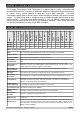
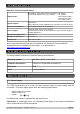
Specifications

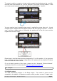
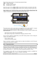

To connect a switch or contact to an input, simply connect the switch between the + and IN+
terminals, and a wire between the – and IN– terminals. The reverse is just as suitable, i.e. that
you connect a wire between + and IN+ and place the switch between – and IN–.
You may need an input to activate when power is supplied from some other unit. A good
example will be a burglar alarm that applies power to the wires going to the siren. In such a
case, it will be a simple matter of connecting the positive wire to the IN+ input, and the
negative wire to the IN– input.
Please keep in mind that these inputs are designed for 5V to 18V operation. If you require an
input to activate upon the presence voltage above 18V, please see the advanced Technical
manual for details on how to do this.
For an in-depth overview of the inputs, please see the “Advanced Technical Manual”.
(Available on the CD, or on the Internet at http://www.gsmcommander.com)
5.9. Outputs
2 x 8A Relay output
The GSM Commander provides 2 x 8A Relay outputs. The number of outputs can be
expanded by the addition of Expansion modules, which provides an extra 5 outputs each.
© Polygon Technologies. All rights reserved Page 9