
Specifications


Hardware:
We connect the alarm output (12V signal that drives the siren) to one of our inputs as
described in section 5.8. The positive wire from the alarm panel is connected to the IN+
terminal, and the negative wire is connected to IN-.
Configuration:
Using the setup software, we create a behaviour statement that will read as follows:
IF Input 1 Goes Active
THEN Place voice call to +27821231234
We create a second behaviour statement that will read as follows:
IF Input 1 Goes Active
THEN Send “Alarm triggered!” via SMS to +27821231234; +27843214321
The first statement will cause a voice call to be placed to +27821231234 in the event of an
alarm. The second statement will cause a notification SMS to be sent to both +27821231234
and +27843214321.
This is an example of how the GSM Commander can have multiple actions triggered by a
single event (in this case, an input becoming active). Note that the voice call will not “say”
anything when the call is answered. One will typically use Caller ID to identify the GSM
commander number, and this will be enough to let you know that there is something wrong at
home.
9.3. Example 3: Control an appliance
In this example we need to switch a 220V light bulb on or off via a suitable SMS message
from a specific number listed on the GSM Commander.
Hardware:
We connect light bulb to a 220V power source via the output 1 contact on the GSM
commander, exactly as described in section 5.9
Configuration:
Using the setup software, we create a behaviour statement that will read as follows:
IF Message is received, containing “Lights on” from 0821231234 , THEN Activate Output 1.
We create a second behaviour statement that will read as follows:
IF Message is received, containing “Lights off” from 0821231234, THEN Deactivate Output 1.
9.4. Example 4: Gate / garage door opener
In this example we need to open a gate in response to a missed call from any number in a list
of accepted numbers. This is an ideal method to control a communal gate in a complex.
Hardware:
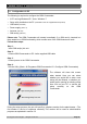
Many gate openers require a pulse to open, and second pulse to close. We will use the
output of the GSM commander to supply this pulse at the position where the open/close
switch is normally connected to the opener.
© Polygon Technologies. All rights reserved Page 20