GSM Commander BASIC Manual For the “GC” Series V3.00 Applicable to firmware package version 6.00 Before Attempting to connect or operate this product, please read these instructions in its entirety, especially the guarantee conditions.
TABLE OF CONTENTS Introduction............................................................................................3 Features..................................................................................................3 Specifications.........................................................................................4 System Requirements...........................................................................4 Installation...................................................................
1. INTRODUCTION The Polygon Technologies GSM Commander is a state-of-the-art, highly configurable and versatile SMS controller. It contains a quad-band integrated GSM cellular engine that allows it to connect to any cellular network to send and receive SMS messages. The GSM Commander can be used to monitor inputs, measure analogue voltages, and remotely control outputs. The GSM Commander is configured using a software program that provides an easy wizard interface.
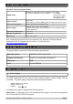
3. SPECIFICATIONS Base Unit Technical Specifications: Digital Inputs: Digital Outputs: Opto-isolated. Inputs draw 10-30mA, depending on the voltage.
In industrial applications, it is advised that the GSM Commander be installed into its own metal housing and be powered from a separate power supply. (As opposed to sharing one with other equipment). Please Note: While the GSM Commander has fairly rugged internal power supply circuitry, no special provision for lightning protection is made.
5.4. Antenna The GSM Commander is supplied with a basic antenna that is suitable for all networks in South Africa. Screw the antenna to its connector on the unit (only finger-tight). Verify using a cellphone, that there is sufficient signal at the proposed installation site. On a phone with a 4 or 5-bar signal strength indicator, you should have at least 1-2 bars of signal. If the signal is too weak, the GSM Commander may have trouble sending or receiving SMS messages.
Screen 3: Click Screen 4: Installation is in progress. When installation completes, click Screen 5: Installation has been completed successfully. Click 5.6. Mounting The GSM Commander is housed in a very durable ABS casing which has 4 protruding tabs, which allows it to be mounted firmly to any surface by means of a screw. Please note: The GSM Commander is not water- or weatherproof. The GSM Commander must be mounted indoors, or inside an appropriate IP65-rated weatherproof enclosure.
Do not mount the GSM Commander inside a steel cabinet, since this will block the cellphone signal. If you have to mount it inside a steel cabinet, you will need to mount a separate antenna on the outside of the cabinet. Suitable antennas can be ordered from Polygon Technologies. See the “Advanced Technical manual” for detail on how to do this. (Available on the CD supplied with the product, or on the Internet at: http://www.gsmcommander.com) 5.7. Dimensions 5.8.
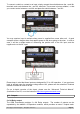
To connect a switch or contact to an input, simply connect the switch between the + and IN+ terminals, and a wire between the – and IN– terminals. The reverse is just as suitable, i.e. that you connect a wire between + and IN+ and place the switch between – and IN–. You may need an input to activate when power is supplied from some other unit. A good example will be a burglar alarm that applies power to the wires going to the siren.
Each of these inputs each have 3 terminals associated with them: COM – Common Terminal N/C – Normally Closed Terminal N/O – Normally Open Terminal When the output is off, the COM and N/C terminals will be internally connected to each other. When the output is on, the COM and N/O terminals will be internally connected to each other. Note that there are small LED indicators next to the output terminals, that will show if the output is ON or OFF.
5.11. Analog Input The GSM Commander provides a single 0-10V analog input, which can be used to measure incoming voltages from sensor devices. Using an appropriate resistor, one can also connect 4-20mA sources to the GSM Commander. What makes this input so special, is that the GSM Commander can interpret the analog value on your behalf. It is perhaps the best to explain this at the hand of a good example.
5.13. Expansion The GSM Commander supports comprehensive expansion by means of the GSM Commander Expansion unit, which provides an additional 5 inputs and 5 outputs similar to the ones found on the GSM Commander itself. A total of 6 Expansion units may be daisy chained to provide a maximum of 30 outputs and 30 inputs* in addition to those on the GSM Commander itself. 12V input on Expansion Each Expansion unit has a 12V input, so that it could also be powered by a separate power supply.
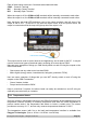
5.14. Status LEDs The GSM Commander has 2 LEDs to show the current status of the GSM Commander. The red LED, labeled “GSM”, shows the status of the internal GSM cellular engine, while the green LED, labeled “STATUS”, shows the status of the GSM Commander as a whole.
6. CONFIGURATION 6.1. Configuration via PC The following is required to configure the GSM Commander: ➢ A PC running Windows XP / Vista / Windows 7 ➢ Setup utility installed on the PC (Available on the CD supplied with the product) ➢ USB cable (Provided) ➢ Power supply (See 5.1) ➢ Antenna (See 5.4) ➢ SIM card(s) (See 5.3) Please note: The GSM Commander will startup immediately if no SIM card is inserted, but there would be no GSM functionality, which means none of the GSM features will work.
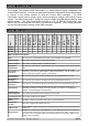
6.2. Behaviour Statements The GSM Commander is configured by defining a number of behaviour statements. Each statement takes the form of an IF-THEN pair. You are thus able to select certain trigger conditions that will cause desired actions to be performed. Any combination of IF and THEN parts can be assembled into complete statements using the configuration software. The GSM Commander can accept up to 128 separate behaviour statements, depending on the model .
➢ IF Date/Time is X • Everyday • Day-of-Week • Specific Date Range ➢ ➢ IF Startup IF GSM Signal Strength • Above X • Below X ➢ IF Statement X Triggers 6.2.2.
6.3. Configuration via SMS The GSM commander provides functionality to provide some configuration changes to be done via SMS message (from the administrator number only). Note that the unit cannot be setup by SMS only. A PC is still required to perform the initial setup. Thereafter, some simple changes to the setup may be done using SMS messages. Please note: The Configuration SMS is NOT case sensitive.
6.3.5. Add a Number to the list* This command can only be sent from the administrator number. To add a number to the list, the administrator must send: ADMIN ADDN 0831234567 The GSM Commander will reply with a confirmation message. 6.3.6. Remove a Number from the list* This command can only be sent from the administrator number. (+27831234567) from the list, the administrator must send: To remove a number ADMIN REMN 0831234567 The GSM Commander will reply with a confirmation message.
Your airtime top-up voucher is typically a long number, and when using this voucher number with a normal cellphone, you typically need to frame this number by some preceding and appending text. For example, with MTN in South Africa, you need to send: “*141*0000000000000#” where the “141” is network-dependent, and the 0000000000000 is the voucher number. This detail is typically provided on the voucher slip.
Hardware: We connect the alarm output (12V signal that drives the siren) to one of our inputs as described in section 5.8. The positive wire from the alarm panel is connected to the IN+ terminal, and the negative wire is connected to IN-.
Configuration: Using the setup software, we create a behaviour statement that will read as follows: IF a Voice Call is received from any listed number, THEN Activate Output 1 for 1 Sec, Pause for 20 Sec, Activate again for 1 Sec. 9.5. Example 5: Contact to Contact relay In a few instances it may be necessary to transmit the status of a contact to a remote point. Let us use an alarm as example.
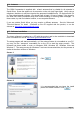
10. FIRMWARE UPDATES Step 1: Download the “setup.exe” executable file from our website (http://www.gsmcommander.com) Step 2: Run the executable file (See 5.5) Step 3: Connect GSM Commander to PC via the supplied USB cable Step 4: Connect power to the GSM Commander Step 5: Run the Utility (Start > All Programs > GSM Commander V6 > Update Firmware) Screen 1: The loader utility will show this screen when started.
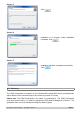
Step 1: Connect USB Cable to GSM Commander (ONLY USB, and not the Power) Press “Windows key” and “Pause” simultaneously on your computer keyboard. This will bring up the “System properties” window as below: Step 2: Select “Device Manager”. This will open the device manager window as below: Double Click on “Universal Serial Bus(USB) controllers” In the list of USB controllers, you should see an item called “GSM Commander”. If this item is not present, the drivers are not installed correctly.
11.3. GSM Commander does not send any SMS messages. Cause 1: Airtime problem The airtime on your SIM card may be depleted, or the SIM card may have been de-activated by the network. Refer to Section 5.3 (Installation: Sim Card) Cause 2: Reception problem You may have bad reception in your area, preventing the unit from connecting to the network. Please check using a regular cellular phone that there shows 1-2 bars of signal right next to the GSM Commander. Refer to Section 5.
A decision about issues A and B will be at the sole discretion of Polygon Technologies. This guarantee does not provide for shipping costs. This will be for the account of the user under all circumstances. 13. IMPORTANT NOTICE (DISCLAIMER / COPYRIGHT) Herein, “the Company” will mean: Polygon Technologies CC, its directors, members, employees and agents. Much effort has been made to ensure the contents of this manual are complete and without errors.