
System information


17-Nov-2014 G2T Programmers Guide Rev-A
99
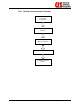
10.2.3. Mechanical Connections
Damage to power and control pins may occur when modules
have been forced into place. Remove the module and, with a
strong light, examine all power and control connector pins within
the mainframe to ensure that they are not damaged.
Install the module and verify that the power and control
connectors mate properly. Ensure that the module captive
fasteners are tight.
Damage to signal cables may occur if signal cables have been
pulled or subjected to continuous movement. Examine the signal
cables for bent or improper routing. Excessive bends or recurring
movement may weaken and fatigue signal cables.
Damage to relay connector jacks may occur when signal cable
connectors have been over tightened. Examine relay connector
jacks at the signal connector panel. Ensure that the signal cable
connectors are tight.
NOTE: Be careful when tightening SMA connectors. The maximum
torque rating that can be applied is 8 inch-pounds. Over
tightening can damage the SMA connectors.
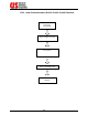
Damage to power and control pins may occur when the CPU has
been improperly installed or forced into place. Remove the CPU
and, with a strong light, examine all power and control connector
pins within the mainframe to ensure that they are not damaged.
Verify that the CPU is fully seated and secured with attaching
hardware.
Damage to power and control pins may occur when power
supplies have been forced into place. Remove the power supply
and with a strong light, examine all power and control connector
pins within the mainframe to ensure that they are not damaged.
Verify that the power supplies are fully seated and secured with
captive fasteners.