
System information


G2T Programmers Guide Rev-A 17-Nov-2014
48
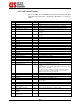
Code
Title
Access
Function
(LS)
75
CPU-1 has GPIB port installed
RO
0 is no, 1 is yes
76
CPU-2 has GPIB port installed
RO
0 is no, 1 is yes
77
DHCP Client (Enable/Disable)
RW
0 is Disable (default), 1 is Enable
78
Network ID Number
RW
A number between 0 and 255. Default is “0”. See note 6.
79
Power Supply Monitoring
Disabling
RW
0, 1, 2 or 3. Where:
0 – both power supplies are monitored.
1 – power supply 1 is not monitored.
2 – power supply 2 is not monitored.
3 – no power supply is being monitored. See note 7.
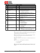
80 Dual Fault Condition Mask RW A number between 0 and 15. Default is “0” for backwards
compatible but a different factory default can be specified
for each project. See note 8.
83 The Pole to which the module
belongs
RW Set: (See Note 2) Get: for a valid Pole, returns -1. For a
module, returns the pole to which it belongs. For the case
where Pole 0 is invalid, returns 0.
84
LSI Identification. Blinking on
the front panel.
RW
0, or 1. Where:
0 – Off (default)
1 – On
85 CPLD Code Revision RO Returns current revision code of the CPLD firmware installed
on the CPU.
86 Serial communication mode RW 0 – 3. Where:
0 – RS-232C (default)
1 – RS-485 with termination
2 – RS-422A without termination
3 – RS-485 without termination
4 – RS-422A with termination
88
Internal ganging on S256XE
systems
RW
0, 1, or 2. Where:
0 – No ganging (default)
1 – Series ganging
2 – Parallel ganging
89 Number of missing modules RW 0 – None, fully populated system (See Note 9)
N-X – Where :
N= The number of modules in a fully populated system
X= The number of modules currently installed.
Note 1: As long as the register's corresponding bit in SESR is set, the GET? Command
returns the last error. Once the SESR has been cleared (by the *ESR? Query), it
returns the last error on the next call then clear itself.
Note 2: The SET determines which module or slot the next GET? references. Example:
to find out which slots module 1 & 2 are in, the following may be used:
set 5,1; get? 5; set 5,2; get? 5
Note 3: This is shared between all the interfaces. The Fault bit in the SBR clears once
it is empty.
Note 4: The “Access” column designations are defined as:
• RW = Read and Write
• RO = Read Only
Note 5: Some systems have the capability to have two CPU’s installed. Those with
only one CPU slot (or built-in like the G2T400CE mainframe) only have “CPU-1”
installed.