Rev-A
CONTENTS CONTENTS ...................................................................................................................... 1 1. INTRODUCTION .................................................................................................... 7 2. G2T FRONT PANEL .............................................................................................. 9 2.1. Power-up Splash Screen ..........................................................................................................
5.1. Changing Between Control Protocols .................................................................................... 33 5.2. IEEE 488.2 Compliant Command Set...................................................................................... 34 5.2.1. System Specific Commands - Tri-Stage ............................................................................ 34 5.2.2. Syntax Conventions .........................................................................................................
9.4. Switch State .............................................................................................................................. 87 9.5. Diagnostic ................................................................................................................................. 88 9.6. Firmware Maintenance ........................................................................................................... 89 9.7. Administrator Account ............................................
TECHNICAL SUPPORT Phone Fax Email +1 818-381-5111 +1 818-252-4868 support@uswi.
G2T Programmers Guide Rev-A 6 17-Nov-2014
1. Introduction The Programmers Guide documents a variety of information that is common to many Universal Switching Corporation products.
G2T Programmers Guide Rev-A 8 17-Nov-2014
2. G2T Front Panel This section describes the features of the G2T front panel which includes an LCD capacitive touchscreen. The touchscreen will respond to touches by an electrical conductor such as a human finger or a capacitive stylus. The display showcases the following features: • 4.
2.2.
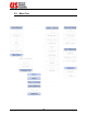
2.3. Home Screen This section describes the features and functions of the home screen. The home screen is the default view after the initial power on sequence is complete. It is also the main screen from which all other screens are accessed. 2.4. Keypad When necessary the numerical keypad will be brought into view.
2.5. Last Action The Last Action Window of the home screen will show the results of the last action performed on the switch. Examples include crosspoint connections, verifications, memory recall, etc. It will report actions applied via the front panel or remote interface(s). 2.6. Application Title The Application Title can be used to identify a specific task for the system so that identification can be made by the operator.
2.8. Disconnect The Disconnect function will launch a sub-menu that allows the user to disconnect an input from an output. Touch the desired field for data entry to activate the keypad. Enter the numerical value of the I/O then press the “OK” button. When all required fields are complete, press the Enter button to submit the action. Pressing back will cancel the action.
2.9. Store and Recall Switching Configurations The System can store and recall different configurations from the CPU’s memory. When a configuration is stored, the entire switching array configuration is saved into the storage memory location. This is useful when changing between configurations. Touch the desired field for data entry to activate the keypad. Enter the numerical value of the memory location then press the “OK” button.
2.10. Verify The Verify function will launch a sub-menu that allows the user to verify the connection status of a specific crosspoint. Touch the desired field for data entry to activate the keypad. Enter the numerical value of the I/O location then press the “OK” button. When all required fields are complete, press the Enter button to submit the action. Pressing back will cancel the action. 2.11.
2.11.1. Mod The Mod button should be used to select the module you want the crosspoint to be applied to. This may not be applicable in all configurations and you should refer to the System Operators Manual for your system to determine how many modules are available and their input / output configurations. 2.12. Menu The Main Menu contains the following sub-menus: 2.12.1. Clear Connections This function will clear all of the crosspoints on the system. You will be prompted to confirm this action or cancel.
2.12.2. Configure Unit This Configure Unit sub-menu contains the following configuration options. 2.12.2.1. CPU-1 / CPU-2 This is where the Ethernet and Serial communication ports are configured. 2.12.2.1.1. IP Address: Network If a static IP address is to be used, enter it here. Otherwise a DHCP address will be used. Subnet Mask: Enter the subnet mask of your LAN Default Gateway: Enter the default gateway of your LAN.
2.12.2.1.2. Serial The serial settings menu allows you to configure the serial port to match the serial settings of your host. By pressing any of the available settings, a drop down menu will be activated. Use your finger to scroll through and select the appropriate settings for your environment.
2.12.2.2. Power-Up Setting These are global settings that take effect after power-up. They include: 2.12.2.2.1. Auto Interlock Two (2) modes of “AUTO INTERLOCK” control are available. With the Auto-Interlocking feature enabled (On), the unit automatically disconnects any input connected to the specified output port (or relay port) before making the new input connection.
NOTE: (On). The factory default is Auto-Interlock mode enabled To change the setting, slide the toggle to the On or Off positions. 2.12.2.2.2. Power On AutoRestore The Power On AutoRestore parameter may be enabled (On) or disabled (Off). When enabled, the unit automatically restores the last configuration from before the unit was powered OFF (or power was lost to the unit). When disabled, all cross-points are automatically cleared on power ON.
2.12.2.3. User Preferences In the User Preferences menu, you may adjust the backlight brightness and background color from the available options. If required, the display firmware may also be updated from this menu. Contact the factory for additional details. 2.12.2.4. Clock / Date Use the scroll wheels to set the current date and time for the real time clock functions.
2.12.2.5. Diagnostic The default view of the Diagnostic screen shows the current module population. Empty, non-operational, or non-recognized modules are shown with a dash ( - ). Modules that the CPU expects to be installed but are not detected are designated with an “X”. Expected and installed modules are shown in order from top to bottom with their accompanying slot number. 2.12.2.5.1. Self Test If selected, a self test will be executed. The display will flash “Updating List….
2.12.2.5.2. Voltage When selected, the voltage menu will appear. This screen shows the status of the power supply voltages in the system. It is divided into three columns including the Main, PSU1 and PSU2. Main: This is the voltage level as seen from the CPU processor (after the diode). It is a combination of voltages in redundant systems. PSU1: This is the voltage being read by the power supply monitoring board in Power Supply 1.
User Description: User defined description of the system that can be changed from the web GUI. By default, it is the same as the System Description. 2.12.4. Lock Screen The front panel controls may be locked by the user to avoid unintentional configuration changes. To lock the front panel, punch in a lock code then press Enter. Valid lock cades are anywhere from 1 to 9999. Once the front panel is locked, it must be unlocked before regaining access.
2.13. LAN Status Indicator The LAN Status Indicator (LSI) is shown in the top right corner of the display and provides multiple functions: 2.13.1. Front Panel ID When the Front Panel ID mode is enabled via the web interface (See Section 9.1) or via remote GET?/SET value 84 (See Section5.2.3) , the LSI will flash on and off. This allows a remote control user of the device to determine which device is being communicated with if they are in an environment with multiple devices of similar model or appearance.
G2T Programmers Guide Rev-A 26 17-Nov-2014
3. STO Commands The following STO commands executed from the front panel are currently applicable: • STO 213 Press the STO button on the front panel keypad and 213 to perform a self-test or verify module(s) installation. • STO222 Press the STO button on the front panel keypad and 222 to set the switching system to 488.2 protocol. • STO 223 Press the STO button on the front panel keypad and 223 to set the system to backwards compatibility.
G2T Programmers Guide Rev-A 28 17-Nov-2014
4. Communicating with the System This system offers flexibility for remote control by offering a variety of interfaces. Remote control over may be established over any or all of the interfaces simultaneously. These interfaces include: • TCP/IP (Ethernet). The embedded CPU supports 10/100 Base-T Ethernet networks, is LXI and SNMP compliant. See Section 8.1.1 for more details • RS-232C/422A/485. Also known as serial interface were originally developed for modems and data terminals.
4.1. Remote Resources The most versatile way to communicate is through Virtual Instrument System Architecture (VISA) library. Typically, this API contains a series of functions designed for interface-independent, device-independent and platform-independent access to instruments connected to a "host". To use, the calling program calls the function viOpen() with a "resource name" as one of the arguments.
4.1.1. Example Resource Descriptors Examples of resource descriptors are: • GPIB0::20::INSTR The instrument at address 20 on GPIB interface card 0. • ASRL1::INSTR The instrument connected to serial port 1. • TCPIP::10.100.1.49::7145::SOCKET The instrument at the indicated IP addresses listening in on port 7145. 4.1.2. GUI and Commands Line Level of Control At the GUI and command line levels, there are several ways to control the instrument. One of the most popular is HyperTerminal from Hilgraeve.
G2T Programmers Guide Rev-A 32 17-Nov-2014
5. Remote Control Commands The system can be controlled through any of the remote interfaces available on the CPU controller. The control commands are the same regardless of the interface in use. Universal Switching products utilize a 488.2 compliant control protocol. For support of older US2, US3 US4, and MSC control protocols, contact Customer Support. 5.1. Changing Between Control Protocols The 488.2 protocols are the factory default and are enabled when a system is delivered from the factory.
5.2. IEEE 488.2 Compliant Command Set 5.2.1. System Specific Commands - Tri-Stage The architecture of Tri-Stage systems allow for specific commands applicable to the following systems. • S2560E-xx-xxxxx • S2561E-xx-xxxxx The operand range of the following commands must be from 1 to the highest acceptable value for the system. The use of ANY or ALL is not acceptable 5.2.1.1. EXClude command This command is used to exclude a particular signal path.
5.2.2. Syntax Conventions The following outlines the proper syntax of the commands for the 488.2 protocol: • Words in the format XXXxxxxx represent keywords. The upper case part is required; the lower case part is optional. Any combination of upper and lower case characters is acceptable (example: CONnect - the CON is required and minimally acceptable).
5.2.2.1. CONnect command This command is used to make a connection within the system. CONnect [FRom] [OUtput] output, [TO] [INput] input [, [ON] [[MOdule] module | Any ] examples: • CONnect from output 1, to input 1 • CON 1,1 (identical to the above) • CON 1,1,any 5.2.2.2. DISconnect command This command is used to perform disconnections for crosspoints (switchpoints) which are currently connected.
5.2.2.4. BREak? command The BREak? query is identical to the disconnect command except that it returns an integer response: • zero: • non-zero: disconnect failed due to an execution error or a fault. disconnect completed successfully This is a departure from other queries which do not return a response if there was an execution error or a fault. If the MAKe? or BREak? queries are used in a compound command and there's an execution error or a fault, execution continues and a response is returned.
A non-zero result indicates the need to check systematically the various status registers to determine the exact problem. It does not indicate the nature of the problem. The actual value returned is at best meaningless and at worst, misleading. A non-zero result is of no value in determining what the problem is only in determining that there was a problem.
The following is an example response to the “que? all” command, which displays a single string from the output to the input connection. que? all response is 1,2 Interpreted as: 1 output, output 1 is connected to input 2 5.2.2.6. GET? and SET commands These commands allow the user to get and/or set various properties and values of the system. GET? property SET property, value Various "properties" can be "set" with a value; Some "properties'" "value" can be read.
5.2.2.7. LOCk and UNLock commands These commands allow the user to lock and/or unlock the front panel keypad. LOCk nnnn (any number from 1 - 9999) UNLock Use the lock and unlock commands as necessary. The code is not required to unlock the keypad remotely. Sending UNLock returns the front panel status to unlocked. examples: • LOCk 2121 locks front panel keypad with code 2121 • UNLock unlocks front panel keypad 5.2.2.8.
examples: • *SAV 99 (saves current switchpoint configuration to memory location 99) • *RCL 12 (recalls switchpoint configuration saved in memory location 12) 5.2.2.10. FORceclose command: Force close command closes all TCP/IP ports. New sessions can be established immediately. example: • FORceclose (closes all open TCP/IP ports) From the front panel keypad, this command can be executed using STOre 224.
5.2.2.12. *IDN? command This command returns an identification string. *IDN? Returns an identification string of the format: Universal Switching,pppppppp,s,rrrrrrrrrr\n where pppppppp is the model code, s is 0 (in lieu of a serial number) and rrrrrrrrrr is the revision code. The model code and the revision code are extremely important for resolving support issues. Note that the revision code is subject to change with any firmware updates/revisions. 5.2.2.13.
5.2.2.15. *CLS command This command clears registers as described below. *CLS This clears the interface’s Last Error Registers, Event Status Register and the Status Byte Register (except for MAV, FLT and PSFLT) but not its queued responses. It has no affect on the other interfaces. As a departure from the standard, the Fault Queue is not affected. As a result, after the command, MAV, FLT and PSFLT reflects the status of their underlying conditions. 5.2.2.16.
5.2.2.19. *ESE? command This command reads the Event Status Enable Register (ESER). *ESE? Returns the current value of the ESER. 5.2.2.20. *SRE command This command sets the value of the Service Request Enable Register. *SRE n Sets the value n (n can be from 0 to 255) in the Service Request Enable Register (SRER). 5.2.2.21. *SRE? command This command reads the value of the Service Request Enable Register. *SRE? Returns the current value of the SRER. 5.2.2.22.
5.2.2.24. *OPC command This command sets the OPC bit in the ESR. *OPC Sets the OPC bit in the ESR. This causes the SBR to be updated. The bit can only be cleared by *CLS or ESR?. 5.2.2.25. *OPC? command *OPC? Immediately returns 1. 5.2.2.26. *WAI command This command is only included for compatibility to the 488.2 standard. *WAI Since the device does not support “over-lapped” commands, this command does nothing. It is included for compatibility with the standard.
5.2.3. GET? and SET Values Below is a table of the available properties that can be read and changed. Note that each one behaves differently so consult the table.
Code 37 Title Access Function 42 “This” CPU’s Current Subnet Mask (MS) “This” CPU’s current Subnet Mask “This” CPU’s current Subnet Mask “This” CPU’s current Subnet Mask (LS) CPU-1 IP Address after reset (MS) CPU-1 IP Address after reset RW nnn of XXX.nnn.XXX.XXX for IP address after next reset 43 CPU-1 IP Address after reset RW nnn of XXX.XXX.nnn.XXX for IP address after next reset 44 RW nnn of XXX.XXX.XXX.nnn for IP address after next reset RW nnn of nnn.XXX.XXX.
Code Title Access Function (LS) 75 CPU-1 has GPIB port installed RO 0 is no, 1 is yes 76 CPU-2 has GPIB port installed RO 0 is no, 1 is yes 77 DHCP Client (Enable/Disable) RW 0 is Disable (default), 1 is Enable 78 Network ID Number RW A number between 0 and 255. Default is “0”. See note 6. 79 Power Supply Monitoring Disabling RW 80 Dual Fault Condition Mask RW 83 The Pole to which the module belongs RW 84 LSI Identification. Blinking on the front panel.
Note 6: When a CPU receives a UDP packet, either addressed to it or as a broadcast on port 5417 of at least one character, the CPU responds with a UDP packet with the format "PROJECT_ xxx" where PROJECT_ is the eight character product code and xxx is the Network ID, with any leading zeros (Example: 11888101 007). The application for this is when DHCP is used. By sending out a broadcast packet addressed to port 5417, one can discover which IP addresses were assigned to what products by their DHCP server(s).
Note 10: A bit weighted value: Bits 0-2: baud rate – decimal values 0: 1200 4: 19200 1: 2400 5: 38400 2: 4800 6: 57600 3: 9600 7: 115200 Bit 3: reserved for RTS/CTS enable Bit 4: reserved for odd parity Bit 5: reserved for even parity Bit 6: reserved for 2 stop bits. The case where both bits 3 and 4 are low is no parity. The default is 3: 9600, no handshaking, no parity and one stop bit.
6. Remote Control Information This section provides a detailed description of the Status Byte Register control protocol and the System Switching Modes. 6.1. Status Byte Register The Status Byte Register tracks and reports the operating status of the system using the IEEE Standard 488.2 control protocol. 6.1.1.
6.1.2. The Status Byte Register (SBR) The current bit status is summarized in the standard Status Byte Register (SBR). The SBR consists of the following bits with the following weights: • The standard Master Summary Status (MSS, numeric weight of 64) – this bit is dependent on the state of the other bits of the register and the current value of the Service Request Enable Register (SRER, see below for details on it and how the MSS is determined).
6.1.2.1. Reading the Status Byte Register (SBR) The SBR is read by issuing the *STB? Common command and interpreting the response. The response is a decimal number that, in practice, is be between 0 and 127. The value indicates which of the five bits are set or cleared. The SBR is read-only. On GPIB interfaces, the SBR is returned to the host in response to a serial poll. The 488.1 Request Service bit (RQS) is returned instead of the MSS bit in this case. For details, please consult the 488.2 standard.
6.1.4. The Event Status Enabled Register (ESER) In a similar situation, each bit in the standard Event Status Enabled Register (ESER) corresponds to a bit in the Event Status Register (ESR, see below). All eight bits in both registers are defined. If at least one bit in the ESER and its corresponding bit in the ESR are set, then the ESB bit of the SBR is set, otherwise the ESB is cleared.
The FLT bit of the SBR tracks the condition of the Fault Queue. The Fault Queue (see below) is a list of “faults” detected by the system. Faults require operator and/or manufacturer intervention. See below. The FLT bit can be monitored by the host to detect such conditions. Additionally, its corresponding bit in SRER can be set and thus cause a service request in the event of a fault. 6.1.5. The Event Status Register (ESR) The standard Event Status Register (ESR) tracks several events.
• Query Error (QYE, weight 4) It indicates that the device was addressed to talk when the output queue was empty or that a new command was received before the output queue was emptied. Both cases are possible under GPIB, but highly unlikely with other interfaces. • Request Control (RQC, weight 2) It is not used and always clear. • Operation Complete (OPC, weight 1) Execution of the *OPC common command causes this bit to be immediately set.
The Last Command Error (LCE), Last Execution Error (LEE) and Last Query Error (LQE) registers and their behavior are specific to UNIVERSAL SWITCHING products. As indicated above, when one of the errors is encountered, a numeric error code placed in one of the registers and its flag in ESR is set. The error code can be read using the GET? Command with the code for that register.
6.1.6.2. The Fault Queue The Fault Queue is a FIFO queue of system faults. Faults require intervention by either the operator (plug in the power supply that the janitor unplugged), or the manufacturer (repair the power supply that failed). The queue can be read with repeated calls to the fault FIFO using the get? 15 command. If it’s empty, get? 15 returns a 0. If the queue should fill-up, it over-writes the older entries in a “circular” fashion.
• The ESR contains several bits which in practice indicate the success or failure of a command to execute and respond. It is set by the various conditions and read by the *ESR? Command. Reading it clears it. • The ESER is “and’ed” with the ESR to generate the SBR’s ESB bit. It is written with the *ESE command and can be read with the *ESE? Command. • Set CME, EXE or QYE bits in the ESR indicate that an error code is stored in LCE, LEE or LQE. These are read by GET? Xx.
6.1.8. Commands to Evaluate and Control Status (488.2) The following commands are used to evaluate and control the status of the device. Unless noted, these commands are part of the IEEE 488.2 standard command set. Recall that each interface maintains its own set of registers (but share the Fault Queue). *STB? – returns the value of the SBR at the start of the command. Note that the effect of the command on MAV won’t be visible until after the command is executed.
*PSC? – returns the current value of PSC *CLS – This clears the interface’s Last Error Registers, Event Status Register and the Status Byte Register (except for MAV, FLT and PSFLT) but not its queued responses. It has no affect on the other interfaces. As a departure from the standard, the Fault Queue is not affected. As a result, after the command, MAV, FLT and PSFLT reflects the status of their underlying conditions. *RST – This command clears all the switchpoint routings in all the modules.
6.1.9. Overlapped Processing The due to the nature of switching operations, all commands are processed sequentially. There is no overlapped processing. As such the following commands are included for compatibility with other 488.2 devices. They provide no added functionality beyond performing their required functions in as little time as possible. Per the standard these operations wait while the no-operationpending flag is false.
6.2. System Switching Mode The switching system can be enabled in two modes; AUTO-ROUTE mode or GANGED mode. The mode of the system affects the allowed syntax for the following operational commands: • CONnect Makes a connection within the system. • DISconnect Makes a disconnection within the system. • QUEry Queries the complete system or a single switchpoint. Depending upon the system mode, these commands may or may not require a module number in the command syntax entered by the user. 6.2.1.
6.2.2. Parallel Operation PARALLEL operation requires a module number in the command string to correctly interpret the command entry. The PARALLEL system is configured to control each module individually. When controlling each module individually, if ALL is specified in the command syntax, the command operation is performed collectively on all modules. • When Module 1 is specified in the command syntax, the command operation is performed on Module 1.
For systems configured in GANGED mode, POLES or “virtual modules” may be formed to assist the programming and operation of the system. 6.2.4. Poles (Virtual Modules) The concept and functionality of POLES or “virtual” modules is summarized as follows: • POLES are used only in PARALLEL systems. • POLES are “virtual” modules that gang together two or more “actual” modules. The system can have as many POLES as required. • Operation on a POLE affects all the module’s members of the POLE.
G2T Programmers Guide Rev-A 66 17-Nov-2014
7. Error Code List The following is a standard list of error codes. Please note that some codes may not be applicable to all types of equipment or configurations. See notes at the bottom of the table for applicability and other information. The types of errors are divided into four classifications: 1. 2. 3. 4. E = Execution C = Command F = Fault Q = Query All errors are 1 or 2-digits (except faults which are 3 to 4 digits). The first two digits are defined in the table below.
Type F F F F E F F F F F F F F F C C C C C C C C Q F F F F F F F F F F F F F F Error 40 41 42 43 47 50 52 53 54 55 56 57 58 59 61 62 63 64 65 66 67 68 73 74 75 76 77 78 79 80 81 82 83 84 85 86 88 Description Power supply #1 fault Power supply #2 fault Power supply #1 is missing Power supply #2 is missing Missing module in system SPI “time-out” error caused by module not responding SPI error (internal) SPI error (internal) SPI error (internal) SPI error (internal) SPI error (internal) SPI error (internal)
8. C3-001 Remote Control Assembly The latest generation CPU, the C3-001 provides the brain and the remote control capacity of the switching system. The CPU offers a host of new features and is compatible with all Universal Switching Corporation switching systems. Below is a list of key features: • SNMP v1, v2 Supported • 10/100BaseT Ethernet • Multi-Serial Control (RS-232C, 422, 485) • USB 2.
8.1.1.1. TCP/IP Control Ports The C3-001 offers a dynamic range of available TCP/IP ports that may be user-defined. The maximum amount of ports that can be set is 15. The factory default active ports are 7145, 7147, 7149, 7151, and 7153. 8.1.1.1.1. Changing the TCP/IP Ports Use the following command sequences to define the port settings: POL? This query returns 15 comma delimited numbers representing the available TCP/IP ports. Ports that are not defined are zero.
8.1.2. Serial The C3-001 offers a standard DB-9 serial port with multi-serial interfaces (RS-232C, RS-422A, and multi-drop RS-485). Additionally, the CPU has a USB 2.0 (Type-A) interface that may be used for remote control. 8.1.2.1. DB-9 Connector 8.1.2.1.1. Changing the Serial Mode The C3-001 CPU is delivered in the default state using the RS-232C control protocol. RS-485 and RS-422A are also available. The serial mode cannot be changed through the front panel.
8.1.2.2. USB (2.0) The USB connector on the C3-001 supports version 2.0 and is TypeA. It may be used as a remote control port to interface with a PC using a terminal program such as Hyperterminal. It may also be used to interface with a GPIB to USB adapter. Universal Switching Corporation has confirmed compatibility with the Prologix, LLC GPIB-USB Controller 6.0. More information on the adapter is available at the manufacturer’s web site: http://prologix.biz/gpib-usb-controller.html 8.2.
8.4. C3-001 CPU LEDs The C3-001 CPU has many LED indicators that provide the following information to the operator: C3 S/N & MAC RST PRG SF ERR Rx Tx MODE 10/100 LED Color Description PRG RED SF GREEN Flashes to indicate that data is being written to serial flash. GREEN Flashes to indicate that data is being written to the microSD card Programming LED. On when the CPU is in Programming Mode. ERR RED On to indicate an execution error or fault condition within the system.
8.5. SNMP v1, v2 The C3-001 currently supports Simple Network Management Protocol (SNMP) v1 and v2. It is ideal for network environments that monitor network-attached devices for conditions that warrant administrative attention. Universal Switching equipment that includes a C3-001 CPU will also include a set of Management Information Bases (MIB’s) that describe the structure of the management data and includes all relevant object identifiers (OID).
Open the SnmpB software and go to the Modules Tab. Under the Available MIB modules window, the three MIB’s will be at the bottom of the list. Select each one and using the right hand facing arrow, move them over to the Loaded MIB modules. Note that additional MIB modules will automatically be added if there are inter-dependencies.
8.5.1.2. General Properties Go to the Tree tab. Using the Remote SNMP Agent drop down menu, select localhost then select the icon for properties. In the General Properties dialog box, enter the IP address of the Universal Switching Corporation switching system and leave the other options set to default settings: Expand the localhost menu and select Snmpv1/v2c. Set both Read community and Write community to public (factory default) or to your custom setting as defined in the web GUI (See Section 9.2).
8.5.1.3. Set Trap Host Currently, the C3-001 CPU supports up to five simultaneous trap hosts. To add your PC to the trap host list, expand the MIB Tree to sysSettings. At the bottom of the sysSettings list you will see trapHostIP. Expand out to trapHostAdress.
In the Select Instance dialog box, double click on 0.0.0.0 In the Set dialog box, the default Syntax drop down should be set to IP address. In the Value field, type in the IP address of the trap host you want to add then select OK. The Query Results window should show that the trap host was added successfully. At this point, all settings are complete to begin using the SNMP interface to communicate with the switching system. 8.5.2. sysSettings.MIB The sysSettings.MIB is displayed in the MIB Tree.
8.5.3. sysTRAP.MIB The sysTRAP.MIB is displayed in the MIB Tree. The OID’s are not interactive. They are simply there to provide the necessary structure to the SNMP manager when a trap is initiated by the switching system. Fault conditions or execution errors will generate a trap. The sysTRAP.MIB is common to all SNMP supported Universal Switching products. You may view traps that have been sent by the switching system by selecting the Traps tab.
8.5.4. swConfig.MIB The swConfig.MIB is displayed in the MIB Tree. In addition to the standard system OID’s, It may also contain the swCMD OID and connectionTable OID which are both optional and availabile for upgrade. The swConfig.MIB is system specific and will contain the swithing systems’s part number as the Object Identifier. In the example below, the Object Identifier is the 12837-S6432-0.
8.5.4.1. swCMD The optional swCMD object is used to connect and disconnect crosspoints in the switching system. Right click on the swCMD object and select set. In the Set dialog box, the default Syntax is Octet String. Type in the command and click OK. In the example below, output 2 is being connected to input 3: Note, compound commands are not supported.
8.5.4.2. connectionTable The optional connectionTable object may be used to query the status of the switching systems crosspoint configuration by right clicking on the object and selecting Table View, The Query Results window displays a table where: Output Index: Lists all output numbers Pole0: Lists the inputs that are connected to the corresponding outputs as seen by pole0. See Section 6.2.4 for more details. A zero indicates that the output is not connected to any input.
9. Web Interface The C3-001 includes a web GUI interface for viewing and changing settings, status, system health, and crosspoint configurations. The web GUI is only available over the Ethernet interface and is compatible with most common web browsers such as Microsoft’s Internet Explorer. This manual section describes each page of the web GUI and its functionality.
9.1. System Information The System information page contains general information about the system. It is read only and available to all users. Access to this page does not require the user to login to the GUI. All subsequent menus require Admin access and the user will be prompted to login. The default user name is admin. The default password is secret.
9.2. LAN Configuration The LAN configuration page provides read / write access to all available network settings. Contact your network administrator for appropriate settings. To program static IP settings, you must first un-check the DHCP enabled check box. Settings are not updated on the system until the “Update” button is selected at the bottom of the page.
9.3.
9.4. Switch State The Switch State page is a dynamic page that allows the operator to view and change existing crosspoint connections. Changes to crosspoint connections are not applied until the “Send Update” button is selected.
9.5. Diagnostic The Diagnostic page provides system health and status. Any reported failures or faults will be displayed in the System Health field. A self test may also be initiated by pressing the TST button.
9.6. Firmware Maintenance The system’s main CPU controller may require firmware updates from time to time to address bugs or customer requested feature changes. This page allows the user to upload the firmware file provided by the USWI support team directly to the system over Ethernet. No additional cables are required.
9.7. Administrator Account This page allows the operator to change the default admin password to something more secure. The password cannot exceed 20 characters.
9.8. Manufacturer Website This link will launch www.USWI.com. If your PC is not connected to the internet, you may receive an error message. 9.9. Support Center This page provides contact information for Universal Switching Corporation.
G2T Programmers Guide Rev-A 92 17-Nov-2014
10. Troubleshooting The series G2T system is robust in design and construction, and extremely reliable in operation. Each system is thoroughly tested and “burned in” at the factory prior to delivery. Usually, problems that occur are minor in nature and may be corrected in the field. This section provides a diagnostic guide for troubleshooting in the field. For problems unable to be diagnosed and repaired in the field, the system or module should be returned to the factory.
10.1.2. Power Supply Four (4) bi-color LED indicators are located on each plug-in power supply assembly. The indicators are driven by the built-in power supply monitoring CPU. If the power supply configuration is redundant, the supply voltage LED’s will come on RED without the power supply’s power switch being “ON”. The power supply monitoring CPU receives power from the other power supply. WARNING: High voltage is present at the power supplies. Never open a power supply while the system is powered ON.
10.1.3.
10.2. Communications Communication problems are usually the result of improper system or host settings, or system configuration compatibility. The IP and port address for the system are different when communicating with Ethernet and serial communications. Verify that the correct IP and port address are entered. Verify that the communications cable is connected to the proper port. System configuration compatibility issues arise when attempting to communicate with a system using the wrong operating mode.
10.2.1.
10.2.2.
10.2.3. Mechanical Connections Damage to power and control pins may occur when modules have been forced into place. Remove the module and, with a strong light, examine all power and control connector pins within the mainframe to ensure that they are not damaged. Install the module and verify that the power and control connectors mate properly. Ensure that the module captive fasteners are tight. Damage to signal cables may occur if signal cables have been pulled or subjected to continuous movement.
10.2.4.
10.3. Performance Degraded performance may result from a signal impedance mismatch. Ensure that the correct impedance is achieved by using cables and connectors for the required impedance. 10.3.1. Compatibility Issues Incorrect system firmware causes compatibility errors. Perform a “*idn?” command from the host PC, and note the firmware that is displayed. Contact Technical Support if you suspect that there is a firmware issue. A firmware upgrade may be available.
10.3.2.
10.4. Technical Support If you have any questions, contact Technical Support for assistance. A dedicated technician is available for immediate consultation. Every effort shall be made to provide customer support. If any portion of the unit is required to be shipped back to the factory for service, contact the factory for an RMA number. NOTE: Most problems may be solved in the field. Contact Technical Support. A technician is available for immediate consultation.
G2T Programmers Guide Rev-A 104 17-Nov-2014
11. Control Software 11.1. RouteWarePRO Our software product called RouteWarePRO is a self-contained graphical interface software package designed specifically to control and monitor Universal Switching Corporation’s products. Designed for ease of use, most users are up and running in minutes. The user can control one “switch box” or many by simply selecting the “box” to be controlled from a menu. GUI colors, channel labeling and configuration uploads are all user definable.
11.2. National Instruments LabVIEW Universal Switching Corporation has developed a VISA library that contains all the drivers necessary to control and monitor our products using National Instruments LabVIEW software. You may download the VISA library by clicking on the link below or visiting our download website: Download Package: http://www.uswi.com/downloads/LabVIEW/USwi%20VISA.zip Website: http://www.uswi.com/Support/downloads.
12. Index Diagnostic .................................................................... 22 Disconnect ................................................................... 13 Home Screen................................................................ 11 Keypad ......................................................................... 11 Last Action ............................................................. 12, 18 Lock Screen ............................................................ 24, 72 Menu.........
Power ................. 9, 19, 20, 23, 46, 48, 52, 55, 68, 93, 94, 95 Power On AutoRestore ..................................................... 20 Power Supply ............................................ 23, 46, 48, 52, 94 RS-232C ..................................................... 29, 48, 69, 71, 73 Q Serial.................................................... 17, 48, 69, 71, 73, 98 Baud Rate..................................................................... 18 Data Bits ...........................
13. Record of Changes This section only applies to revised documents. The table below indicates the revision level entered and a brief description of the change(s). Revision Description of Change Date Initial Release A 17-Nov-2014 20141117 New Cover Page Revised Section 2.1 to reflect modified boot sequence. Revised Section 2.12.2.1.1 to clarify the Network ID function. Revised Section 2.12.2.3. to show new page layout. Updated screenshot in Section 2.12.2.5.2 Updated Section 2.12.3 Added Section 2.