
Installation manual


901265-01K
For more information, visit www.desatech.com
For more information, visit www.desatech.com
7
7
INSTALLATION
Continued
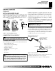
Installation and Gas Connection
1. Place the burner pan assembly in the center of the fireplace
floor. Make sure the front of pan faces forward.
2. Thread the gas supply fitting to the fireplace gas supply pipe.
Use thread sealant.
3. Install adapter fitting onto the burner inlet fitting using
thread sealant on male threads of burner inlet fitting (see
Figure 7). Adjust to most convenient position.
4. Install the gas connector tube to the gas supply fitting. Care-
fully shape tube to attach to adapter fitting. Be careful not to
cause kinks in tube.
OPTIONAL GA9050A ON/OFF SAFETY
VALVE/PILOT KIT ASSEMBLY
For additional convenience and safety, or for propane/LP conver-
sion, an optional ON/OFF safety valve/pilot kit is available. See
Accessories, page 15.
WARNING: You must use a ON/OFF safety valve/
pilot kit for propane/LP conversion.
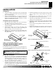
Natural Gas Installation
1. Thread the gas control valve onto the burner inlet fitting (see
Figure 8). Use thread sealant on the male threads of the burner
inlet fitting. Hold the burner inlet fitting with a wrench to pre-
vent overtightening the connection to the burner. Make sure
the control rod is facing the front (see Figure 8).
2. Attach the pilot gas line to the pilot outlet of the gas control valve
and tighten. Connect the thermocouple to the rear of the gas con-
trol valve. See Figure 9. Do not overtighten. If using propane/LP
gas, see Changing Pilot Orifice, page 8.
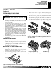
Figure 7 - Connecting Gas to Appliance
Adapter
Fitting
Gas Connector
Tube
Burner Inlet Fitting
Gas Control
Valve
Burner Pan
Assembly
Figure 8 - Installing Gas Control Valve
Control Rod
Burner Pan
Assembly (Facing
Front of Fireplace)
3. Install the inlet fitting into the inlet opening of the gas control
valve (see Figure 10). Use thread sealant on the male pipe
threads.
4. Place the burner pan assembly in the center of the fireplace
floor. Make sure the front of pan faces forward.
5. Thread the gas supply fitting to the fireplace gas supply pipe.
Adjust to most convenient position.
6.
Install the gas connector tube to the gas supply fitting. Carefully
shape tube to attach to adapter fitting. Be careful not to cause
kinks in tube.
7. Test for leaks following instructions under Testing Burner for
Leaks, page 9.
8.
Retighten and adjust the location of the gas control as necessary.
The gas control should be level, with the control rod to the front.
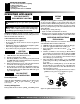
Figure 9 - Gas Control Valve with Thermocouple and Pilot
Figure 10 - Installing Inlet Fitting and Gas Connector Tube
Thermocouple and Line
Pilot and Line
Gas Control Valve
Gas Control
Valve
Gas Inlet
Fitting
Gas
Connector
Tube
Inlet
Opening
INSTALLATION
Hearth Kit Assembly and Installation (Cont.)
Optional GA9050A ON/OFF Safety Valve/Pilot Kit Assembly
6. Using burner clamp, screw, and nut provided, assemble clamp
to pan (“U” style and triple burners only). This will hold the
burner manifold in place.
7. If using optional GA9050A kit, go to Optional GA9050A On/
Off Safety Valve/Pilot Kit section for installation instructions.
If using optional GA9150A kit, follow instructions included
with kit for installation and operation.