
Installation manual


901265-01K
For more information, visit www.desatech.com
For more information, visit www.desatech.com
6
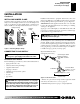
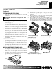
Figure 5 - Checking Gas Joints
HEARTH KIT ASSEMBLY AND INSTALLATION
Kit Assembly - Single and Dual-Flame Only
1. Determine which side the gas line will be coming into the fireplace.
NOTICE: Triple-burner models CBL18/24 or BFLT18/24
come preassembled with gas inlet on right side of
burner pan. DO NOT attempt to reposition burner on
triple-burner models. If your fireplace supply is on the
left side, a longer 3/8" flex line should be purchased and
routed behind burner pan and away from flame area.
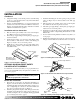
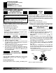
2. Using a hammer and screw driver, remove knockout plug from
the side of the pan that corresponds to the gas line (see Figure 6).
3. Unscrew burner inlet fitting from burner manifold.
4. Place burner manifold in pan with threaded opening facing
open knockout plug.
5. Using thread sealant (resistant to the action of propane/LP
gas) on larger end of fitting, screw the burner inlet fitting
through hole and into burner manifold (see Figure 6). Tighten
using a wrench. If using propane/LP gas, see Propane/LP
Gas Conversion, page 8.
WARNING: Test all gas piping and connections,
internal and external to unit, for leaks after installing
or servicing. Correct all leaks at once.
WARNING: Never use an open flame to check for
a leak. Apply a noncorrosive leak detection fluid to
all joints. Bubbles forming show a leak. Correct all
leaks at once.
CHECKING GAS CONNECTIONS
Pressure Testing Gas Supply Piping System
Test Pressures In Excess Of 1/2 PSIG (3.5 kPa)
1. Disconnect log set and its individual equipment shutoff valve
from gas supply piping system.
2. Cap off open end of gas pipe where equipment shutoff valve
was connected.
3. Pressurize supply piping system by either using compressed
air or opening main gas valve located on or near gas meter.
4. Check all joints of gas supply piping system. Apply noncorrosive
leak detection fluid to gas joints. Bubbles forming show a leak.
5. Correct all leaks at once.
6. Reconnect log set and equipment shutoff valve to gas supply.
Check reconnected fittings for leaks.
Test Pressures Equal To or Less Than 1/2 PSIG (3.5 kPa)
1. Close equipment shutoff valve (see Figure 5).
2. Pressurize supply piping system by either using compressed
air or opening main gas valve located on or near gas meter.
3. Check all joints from gas meter to equipment shutoff valve
(see Figure 5). Apply noncorrosive leak detection fluid to gas
joints. Bubbles forming show a leak.
4. Correct all leaks at once.
INSTALLATION
Continued
Gas Meter
Equipment
Shutoff Valve
INSTALLATION
Checking Gas Connections
Hearth Kit Assembly and Installation
Figure 6 - Installing Burner
Burner Inlet
Fitting
Burner Inlet
Fitting
Screw
Front Burner
Burner
Manifold
Nut
Burner Clamp
Burner Pan
(Front)
Burner Manifold
Knockout
Plugs
Burner Pan
(Front)
Burner Pan
(Front)
Knockout
Plugs
Gas Connection
Must Be On Right
Side For Triple
Burner
Burner Inlet
Fitting
TRIPLE-BURNER
SINGLE-BURNER DUAL-FLAME