UNVENTED (VENT-FREE) GAS LOG HEATER OWNER’S OPERATION AND INSTALLATION MANUAL PFS ® US REMOTE MODELS CSG3924NRC AND CSG3924PRC Remote Models Also Design-Certified As Vented Decorative Appliances WARNING: If the information in this manual is not followed exactly, a fire or explosion may result causing property damage, personal injury or loss of life. — Do not store or use gasoline or other flammable vapors and liquids in the vicinity of this or any other appliance.
TABLE OF CONTENTS Safety................................................................... 2 Unpacking............................................................ 5 Product Identification............................................ 5 Local Codes......................................................... 5 Product Features.................................................. 6 Air For Combustion and Ventilation...................... 6 Installation............................................................
SAFETY Continued WARNING: This product contains and/or generates chemicals known to the state of California to cause cancer or birth defects or other reproductive harm. IMPORTANT: Read this owner’s manual carefully and completely before trying to assemble, operate or service this fireplace. Improper use of this fireplace can cause serious injury or death from burns, fire, explosion, electrical shock and carbon monoxide poisoning.
SAFETY Continued 1. This appliance is only for use with the type of gas indicated on the rating plate. This appliance is not convertible for use with other gases. 2. Do not place propane/LP supply tank(s) inside any structure. Locate propane/ LP supply tank(s) outdoors (propane/LP units only). 3. If you smell gas • shut off gas supply • do not try to light any appliance • do not touch any electrical switch; do not use any phone in your building • immediately call your gas supplier from a neighbor’s phone.
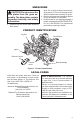
UNPACKING CAUTION: Do not remove the data plates from the grate assembly. The data plates contain important warranty and safety information. 1. Remove logs and heater base assembly from carton. Note: Do not pick up heater base assembly by burners. This could damage heater. Always handle base assembly by grate. 2. Remove all protective packaging applied to logs and heater for shipment. 3. Check heater for any shipping damage.
PRODUCT FEATURES OPERATION This heater is clean burning. It requires no outside venting. There is no heat loss out a vent or up a chimney. Heat is generated by both realistic flames and glowing coals. This heater is designed for vent-free operation with flue damper closed. It has been tested and approved to ANSI Z21.11.2 standard for unvented heaters. State and local codes in some areas prohibit the use of vent-free heaters. This heater may also be operated as a vented decorative (ANSI Z21.
AIR FOR COMBUSTION AND VENTILATION Continued If your home meets all of the three criteria above, you must provide additional fresh air. See Ventilation Air From Outdoors, page 8. If your home does not meet all of the three criteria above, proceed to Determining Fresh-Air Flow For Heater Location, below. Confined and Unconfined Space The National Fuel Gas Code, ANSI Z223.1/ NFPA 54 defines a confined space as a space whose volume is less than 50 cubic feet per 1,000 Btu/hr (4.
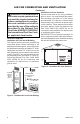
AIR FOR COMBUSTION AND VENTILATION Continued WARNING: If the area in which the heater may be operated does not meet the required volume for indoor combustion air, combustion and ventilation air shall be provided by one of the methods described in the National Fuel Gas Code, ANSI Z223.1/NFPA 54, the International Fuel Gas Code, or applicable local codes. VENTILATION AIR Ventilation Air From Inside Building This fresh air would come from an adjoining unconfined space.
INSTALLATION NOTICE: This heater is intended for use as supplemental heat. Use this heater along with your primary heating system. Do not install this heater as your primary heat source. If you have a central heating system, you may run system’s circulating blower while using heater. This will help circulate the heat throughout the house. In the event of a power outage, you can use this heater as your primary heat source. WARNING: A qualified service person must install heater. Follow all local codes.
INSTALLATION Continued CHECK GAS TYPE Use the correct type of gas (natural or propane/ LP). If your gas supply is not the correct gas type, do not install heater. Call dealer where you bought heater for proper type heater. WARNING: This appliance is equipped for either natural gas or propane/LP gas but not both. Gas type is indicated on the rating plate. Field conversion is not permitted. INSTALLATION AND CLEARANCES FOR VENT-FREE OPERATION WARNING: Maintain the minimum clearances.
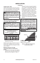
INSTALLATION Continued MINIMUM NONCOMBUSTIBLE MATERIAL CLEARANCES If Not Using Mantel Note: If using a mantel proceed to If Using Mantel. If not using a mantel, follow the information on this page. You must have noncombustible material(s) above the fireplace opening. Noncombustible materials (such as slate, marble, tile, etc.) must be at least 1/2" thick. With sheet metal, you must have noncombustible material behind it. Noncombustible material must extend at least 8" up.
INSTALLATION Continued Determining Minimum Mantel Clearance When Using a Hood If minimum clearances in Figure 6, page 11, are not met, you must have a hood. When using a hood there are still certain minimum mantel clearances required. Follow minimum clearances shown in Figure 7, when using hood. NOTICE: Surface temperatures of adjacent walls and mantels become hot during operation. Walls and mantels above the firebox may become hot to the touch.
INSTALLATION Continued If reasons number 1 or 2 apply to you, you must permanently open chimney flue damper. You must install the damper clamp accessory (to order, see Accessories, page 34). This will insure vented operation (see Figure 10). The damper clamp will keep damper open. Installation instructions are included with clamp accessory. See chart below for minimum permanent flue opening you must provide. Attach damper clamp so the minimum permanent flue opening will be maintained at all times.
INSTALLATION Continued 1. Apply pipe joint sealant lightly to male threads of gas fitting (provided). For Remote models connect approved flexible gas hose to inlet side of gas control (see Figure 11). 2. Position heater base assembly in fireplace. 3. Mark screw locations through holes in front panel of base (see Figure 12). If installing in a brick-bottom fireplace, mark screw locations in mortar joint of bricks. 4. Remove heater base from fireplace. 5.
INSTALLATION Continued For propane/LP units, the installer must supply an external regulator. The external regulator will reduce incoming gas pressure. You must reduce incoming gas pressure to between 11" and 14" of water. If you do not reduce incoming gas pressure, heater regulator damage could occur. Install external regulator with the vent pointing down as shown in Figure 13. Pointing the vent down protects it from freezing rain or sleet. CAUTION: Use only new, black iron or steel pipe.
INSTALLATION Continued CHECKING GAS CONNECTIONS WARNING: Test all gas piping and connections, internal and external to unit, for leaks after installing or servicing. Correct all leaks at once. WARNING: Never use an open flame to check for a leak. Apply a noncorrosive leak detection fluid to all joints. Bubbles forming show a leak. Correct all leaks at once. CAUTION: Make sure external regulator has been installed between propane/LP supply and heater. See guidelines under Connecting to Gas Supply, page 14.
INSTALLATION Continued PRESSURE TESTING HEATER GAS CONNECTIONS 1. Open equipment shutoff valve (see Figure 15, page 16). 2. Open main gas valve located on or near gas meter for natural gas or open propane/LP supply tank valve. 3. Make sure control knob of heater is in the OFF position. 4. Check all joints from equipment shutoff valve (see Figure 16 or 17, page 16). Apply noncorrosive leak detection fluid to all joints. Bubbles forming show a leak. 5. Correct all leaks at once. 6.
INSTALLATION Continued INSTALLING LOGS WARNING: Failure to position the parts in accordance with these diagrams or failure to use only parts specifically approved with this heater may result in property damage or personal injury. Each log is marked with a number. These numbers will help you identify the log when installing. It is very important to install these logs exactly as instructed. Do not modify logs. Only use logs supplied with heater.
OPERATION FOR YOUR SAFETY READ BEFORE LIGHTING NOTICE: During initial operation of new fireplace, burning logs will give off a paper-burning smell. Open damper or window to vent smell. This will only last a few hours. WARNING: If you do not follow these instructions exactly, a fire or explosion may result causing property damage, personal injury or loss of life. 1. STOP! Read the safety information, column 1. 2. Make sure equipment shutoff valve is fully open. 3.
OPERATION Continued 7. With control knob pressed in, press and release ignitor button. This will light pilot. The pilot is attached to the front burner. If needed, keep ignitor button pressed in until pilot lights. Note: If pilot does not stay lit, contact a qualified service person or gas supplier for repairs. Until repairs are made, light pilot with match. To light pilot with match, see Manual Lighting Procedure. 8. Keep control knob pressed in for 30 seconds after lighting pilot.
OPERATION Continued HAND-HELD REMOTE OPERATION BATTERIES WARNING: Make sure your selector switch is in OFF position before installing or changing batteries in your hand-held remote or receiver. For installing or replacing batteries in remote control or receiver, see Installing Batteries in Remote Control and Receiver on page 17. Program receiver to remote on page 23 Low Battery - Hand-Held Remote Control When batteries in hand-held remote control are low, an icon will appear on display.
OPERATION Continued FLAME HEIGHT This function allows you to control the height of flames through 5 levels (see Figure 32). Select the manual flame height function by pressing the MODE button until a flame is shown in the lower left corner of the display. Use UP/DOWN arrow button to set desired flame height for front and rear burner (see Figure 32). A beep from receiver confirms the command.
OPERATION Continued SMART THERMOSTAT The Smart Thermostat adjusts flame height in accordance to differences between set temperature and room temperature. As room temperature gets closer to set temperature the smart function will modulate the flame lower. As room temperature cools, it will modulate the flame higher. To activate this function, press THERMOSTAT button until the word SMART appears to the right of temperature bulb graphic on display. Use UP/DOWN arrow button to set desired room temperature.
INSPECTING BURNERS Check pilot flame pattern and burner flame patterns often. PILOT FLAME PATTERN Figure 37 shows a correct pilot flame pattern. Figure 38 shows an incorrect pilot flame pattern. The incorrect pilot flame is not touching the thermocouple. This will cause the thermocouple to cool. When the thermocouple cools, the heater will shut down. If pilot flame pattern is incorrect, as shown in Figure 38 • turn heater off (see To Turn Off Gas to Appliance, page 20.
CLEANING AND MAINTENANCE WARNING: Turn off heater and let cool before cleaning. CAUTION: You must keep control areas, burners and circulating air passageways of heater clean. Inspect these areas of heater before each use. Have heater inspected yearly by a qualified service person. Heater may need more frequent cleaning due to excessive lint from carpeting, pet hair, bedding material, etc. WARNING: Failure to keep the primary air opening(s) of the burner(s) clean may result in sooting and property damage.
TROUBLESHOOTING WARNING: Turn off heater and let cool before servicing. Only a qualified service person should service and repair heater. CAUTION: Never use a wire, needle or similar object to clean ODS/pilot. This can damage ODS/pilot unit. Note: All troubleshooting items are listed in order of operation. OBSERVED PROBLEM POSSIBLE CAUSE REMEDY When ignitor button is pressed, there is no spark at ODS/pilot 1. Ignitor electrode not connected to ignitor cable 2. Ignitor cable pinched or wet 1.
TROUBLESHOOTING Continued OBSERVED PROBLEM POSSIBLE CAUSE REMEDY ODS/pilot lights but flame goes out when control knob is released 1. Control knob not fully pressed in 2. Control knob not pressed in long enough 1. Press in control knob fully 3. Safety interlock system has been triggered 4. Equipment shutoff valve not fully open 5. Pilot flame not touching thermocouple, which allows thermocouple to cool, causing pilot flame to go out.
TROUBLESHOOTING Continued OBSERVED PROBLEM POSSIBLE CAUSE REMEDY Yellow flame in front burner during burner combustion 1. Not enough air 1. Check burner(s) for dirt and debris. If found, clean burner(s) (see Cleaning and Maintenance, page 25) 2. Replace gas regulator 2. Gas regulator defective Slight smoke or odor during initial operation 1. Residues from manufacturing processes and logs curing 1.
TROUBLESHOOTING Continued WARNING: If you smell gas • Shut off gas supply. • Do not try to light any appliance. • Do not touch any electrical switch; do not use any phone in your building. • Immediately call your gas supplier from a neighbor’s phone. Follow the gas supplier’s instructions. • If you cannot reach your gas supplier, call the fire department. IMPORTANT: Operating heater where impurities in air exist may create odors.
PARTS REMOTE VARIABLE CONTROL MODELS CSG3924NRC AND CSG3924PRC 8 9 8 3 6 4 5 7 8 27 LPG 23 11 24 20 2 1 13 2 12 14 14 26 21 22 10 15 17 19 16 18 25 30 www.fmiproducts.
PARTS REMOTE VARIABLE CONTROL MODELS 1 2 3 4 5 6 7 8 9 10 11 12 13 14 15 16 17 18 19 20 21 22 23 24 25 26 27 ** 111435-01 112465-02 112446-02 103779-01 103778-01 112713-03 098249-01 M11084-26 112782-02DD 123085-02 107186-11 107186-12 107186-09 107186-10 117004-01 M12461-26 099918-02 099387-22 099387-23 122687-01 111440-05 111440-06 103784-01 107634-01 122631-01 112715-01 098271-12 100609-01 123475-01 123085-01 121120-01 Ramp Burner Base Electronic Ignitor Ramp Front Burner Ramp Rear Burner O.D.S.
PARTS MODELS CSG3924NRC AND CSG3924PRC This list contains replaceable parts used in your heater. When ordering parts, follow the instructions listed under Replacement Parts on page 34 of this manual. 3 4 5 2 6 1 KEY CSG3924NRC NO. CSG3924PRC DESCRIPTION 1 2 3 4 5 6 32 121699-11 121699-10 125683-01 121699-09 121699-13 121699-12 Front Right Log Front Left Log Middle Right Log Middle Left Log Bottom Log Rear Log www.fmiproducts.
SPECIFICATIONS CSG3924PRC • • • • • Rating (Variable): 15,000/36,000 Btu/Hr Type Gas: Propane/LP Ignition: Electronic Manifold Pressure: 8.4" W.C. Inlet Gas Pressure (in. of water): Max - 14" W.C., Min* - 11" W.C. *For purpose of input adjustment CSG3924NRC • • • • • Rating (Variable): 14,000/36,000 Btu/Hr Type Gas: Natural Ignition: Electronic Manifold Pressure: 3.5" W.C. Inlet Gas Pressure (in. of water): Max - 10.5" W.C., Min* - 5" W.C.
SERVICE HINTS When Gas Pressure Is Too Low • pilot will not stay lit • burners will have delayed ignition • heater will not produce specified heat • propane/LP gas supply may be low You may feel your gas pressure is too low. If so, contact your local propane/LP or natural gas supplier. TECHNICAL SERVICE You may have further questions about installation, operation, or troubleshooting. If so, contact FMI PRODUCTS, LLC at 1-866-328-4537.
NOTES _____________________________________________________ ______________________________________________________ ______________________________________________________ ______________________________________________________ ______________________________________________________ ______________________________________________________ ______________________________________________________ ______________________________________________________ ______________________________________________________ ___________
WARRANTY KEEP THIS WARRANTY Model (located on product or identification tag)______________________________ Serial No. (located on product or identification tag)___________________________ Date Purchased ___________________________ Keep receipt for warranty verification.