
Install Instructions


Installation and Operation Manual - SVH 09/12/18/24 Series
12
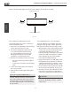
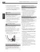
Refer to the following diagram to ensure proper distance from walls and ceiling:
Step 2: Attach mounting plate to wall
The mounting plate is the device on which you
will mount the indoor unit.
1.
Remove the screw that attaches the mounting
plate to the back of the indoor unit.
2.
Place the mounting plate against the wall
in a location that meets the standards in
the Select Installation Location step. (See
Mounting Plate Dimensions for detailed
information on mounting plate sizes.)
3.
Drill holes for mounting screws in places that:
• have studs and can support the weight of
the unit
• correspond to screw holes in the mounting
plate
4. Secure the mounting plate to the wall with
the screws provided.
5. Make sure that mounting plate is at against
the wall.
NOTE FOR CONCRETE OR BRICK WALLS:
If the wall is made of brick, concrete, or similar
material, drill 5mm-diameter (0.2in-diameter)
holes in the wall and insert the sleeve anchors
provided. Then secure the mounting plate to
the wall by tightening the screws directly into
the clip anchors.
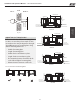
Step 3: Drill wall hole for connective piping
You must drill a hole in the wall for refrigerant
piping, the drainage pipe, and the signal cable
that will connect the indoor and outdoor units.
1.
Determine the location of the wall hole based
on the position of the mounting plate. Refer
to Mounting Plate Dimensions on the
next page to help you determine the optimal
position. The wall hole should have a 65mm
(2.5in) diameter at least, and at a slightly
lower angle to facilitate drainage.
2.
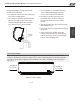
Using a 65-mm (2.5in) core drill, drill a hole in
the wall. Make sure that the hole is drilled at
a slight downward angle, so that the outdoor
end of the hole is lower than the indoor end
by about 5mm to 7mm (0.2-0.275in). This will
ensure proper water drainage. (See Fig. 3.2)
3.
Place the protective wall cu in the hole. This
protects the edges of the hole and will help
seal it when you nish the installation process.
CAUTION
When drilling the wall hole, make sure to
avoid wires, plumbing, and other sensitive
components.
Indoor Unit
Installation
Fig. 3.1-b
12cm (4.75in)
or more
2.3m (90.55in) or more
12cm (4.75in)
or more
15cm (5.9in) or more
W all
Indoor Outdoor
mm7-5
(0.2-0.3in)
Fig.3.2
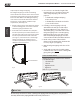
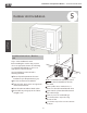
MOUNTING PLATE DIMENSIONS
Dierent models have dierent mounting plates.
In order to ensure that you have ample room to
mount the indoor unit, the diagrams to the right
show dierent types of mounting plates along
with the following dimensions:
•
Width of mounting plate
•
Height of mounting plate
•
Width of indoor unit relative to plate
•
Height of indoor unit relative to plate
•
Recommended position of wall hole (both
to the left and right of mounting plate)
•
Relative distances between screw holes
Indoor Unit
Installation
Fig. 3.2
Left rear wall
hole 65mm (2.5in)
Right rear wall
hole 65mm (2.5in)
Indoor unit
outline
39mm
(1.5in)
39mm
(1.5in)
285mm (11.2in)
47.1mm
(1.85in)
47.1mm
(1.85in)
Model B
Model A
146.5mm(5.76in)
228.5mm(8.99in)
241mm(9.48in)
45mm(1.7in) 101.6mm(4in)
183.6mm(7.2in)
123.6mm(4.86in)
715mm(28in)
805mm(31.7in)
117.5mm(4.62in)
115.6mm(4.55in)
233.1mm(9.17in)
398mm(15.67in)
398mm(15.98in)
Left rear wall
hole 65mm (2.5in)
Right rear wall
hole 65mm (2.5in)
Indoor unit
outline
302mm (11.88in)
36.6mm
(1.44in)
36.7mm
(1.44in)
47mm
(1.85in)
47.5mm
(1.87in)
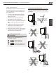
Model C
304.1mm(11.9in)
224.2mm(8.82in)
45mm(1.7in)
259.1mm(10.2in)
100.6mm(3.96in)
123.7mm(4.87in)
958.3mm(37.7in)
Left rear wall
hole 65mm (2.5in)
Right rear wall
hole 65mm (2.5in)
324.9mm (12.79in)
55mm
(2.16in)
47mm
(1.85in)
47mm
(1.85in)
55mm
(2.16in)
Model D
316.7mm(12.4in)
1037.6mm(40.85in)
271.7mm(10.69in)
291mm(11.45in)
246mm(9.68in)
45mm(1.77in)
45mm(1.77in)
Left rear wall
hole 65mm (2.5in)
Right rear wall
hole 65mm (2.5in)
Indoor unit
outline
39mm
(1.5in)
39mm
(1.5in)
285mm (11.2in)
47.1mm
(1.85in)
47.1mm
(1.85in)
45mm(1.7in)
117.5mm(4.62in)
439mm(17.28in)
506mm(19.92in)
Correct orientation of Mounting Plate