Installation and Operation Manual SVH Series Inverter Single Zone Ductless Mini-Split SVH09SA-0 SVH09SA-1 SVH12SA-0 SVH12SA-1 SVH18SA-1 SVH24SA-1 www.marsdelivers.
Installation and Operation Manual - SVH 09/12/18/24 Series Table of Contents Installation Manual 0 Safety Precautions........................... 4 1 Accessories........................................ 6 2 Installation Summary - Indoor Unit........ 8 3 Unit Parts.......................................... 10 4 Indoor Unit Installation........ 1. Select installation location.......................... 2. Attach mounting plate to wall.................... 3. Drill wall hole for connective piping.........
Installation and Operation Manual - SVH 09/12/18/24 Series 6 Refrigerant Piping Connection........ A. Note on Pipe Length................................................ B. Connection Instructions –Refrigerant Piping............. 1. Cut pipe.............................................................. 2. Remove burrs...................................................... 3. Flare pipe ends.................................................... 4. Connect pipes..................................................
Installation and Operation Manual - SVH 09/12/18/24 Series Safety Precautions Read Safety Precautions Before Installation Incorrect installation due to ignoring instructions can cause serious damage or injury. The seriousness of potential damage or injuries is classified as either a WARNING or CAUTION. This symbol indicates that ignoring instructions may cause death or serious injury.
Installation and Operation Manual - SVH 09/12/18/24 Series WARNING 6. For all electrical work, follow all local and national wiring standards, regulations, and the Installation Manual. You must use an independent circuit and to supply power. Do not connect other appliances to the same circuit. Insufficient electrical capacity or defects in electrical work can cause electrical shock or fire. 7. For all electrical work, use the specified cables.
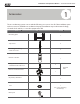
Installation and Operation Manual - SVH 09/12/18/24 Series 1 Accessories The air conditioning system comes with the following accessories. Use all of the installation parts and accessories to install the air conditioner. Improper installation may result in water leakage, electrical shock and fire, or cause the equipment to fail. Name Shape Quantity Mounting plate 1 Clip anchor 5 Mounting plate fixing screw ST3.9 X 25 5 Remote controller 1 Fixing screw for remote controller holder ST2.
Installation and Operation Manual - SVH 09/12/18/24 Series Shape Name Quantity 1 Owner’s manual Installation manual 1 Remote controller illustration Connecting pipe assembly 1 Liquid side Φ 6.35( 1/4i n) Φ9.52( 3/8in) Φ9.52( 3/8in) Gas side Φ12.7( 1/2in) Φ16( 5/8in) 7 Parts you must purc hase. Consult the dealer about the pipe size.
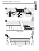
Installation and Operation Manual - SVH 09/12/18/24 Series Installation Overview Installation Summary - Indoor Unit 1 2 15cm (5.9in) 12cm (4.75in) 2 12cm (4.75in) 2.3m (90.
Installation and Operation Manual - SVH 09/12/18/24 Series 6 7 1 Connect Piping (Page 25) 2 3 Connect Wiring (Page 17) 8 Wrap Piping and Cable (Page 18) 9 STEP 8 Mount Indoor Unit (Page 18) 9 Prepare Drain Hose (Page 14) Installation Overview 5
Installation and Operation Manual - SVH 09/12/18/24 Series 3 Unit Parts Installation Overview Wall Mounting Plate Front Panel Power Cable (Some Units) Louver Drainage Pipe Signal Cable Refrigerant Piping Remote Control Remote Holder (Some Units) Fig. 3.1 NOTE ON ILLUSTRATIONS Illustrations in this manual are for explanatory purposes. The actual shape of your indoor unit may be slightly different. The actual shape shall prevail.
Installation and Operation Manual - SVH 09/12/18/24 Series 4 Indoor Unit Installation Indoor Unit Installation Fig. 3.1-a Installation Instructions – Indoor Unit PRIOR TO INSTALLATION Before installing the indoor unit, refer to the label on the product box to make sure that the model number of the indoor unit matches the model number of the outdoor unit. Step 1: Select installation location Before installing the indoor unit, you must choose an appropriate location.
Installation and Operation Manual - SVH 09/12/18/24 Series Refer to the following diagram to ensure proper distance from walls and ceiling: 15cm (5.9in) or more 12cm (4.75in) or more 12cm (4.75in) or more Indoor Unit Installation 2.3m (90.55in) or more Fig. 3.1-b Step 3: Drill wall hole for connective piping You must drill a hole in the wall for refrigerant piping, the drainage pipe, and the signal cable that will connect the indoor and outdoor units.
Installation and Operation Manual - SVH 09/12/18/24 Series Indoor W all Outdoor 398mm(15.67in) 233.1mm(9.17in) 39mm (1.5in) 39mm (1.5in) 47.1mm (1.85in) 285mm (11.2in) Indoor unit outline 47.1mm (1.85in) 5-7m m (0.2-0.3in) 146.5mm(5.76in) Left rear wall hole 65mm (2.5in) 115.6mm(4.55in) 117.5mm(4.62in) 45mm(1.7in) 101.6mm(4in) Right rear wall hole 65mm (2.5in) 715mm(28in) Indoor Unit Installation Model A Fig. 3.2 Fig.3.2 39mm (1.5in) 47.1mm (1.85in) Indoor unit outline 47.1mm (1.
Installation and Operation Manual - SVH 09/12/18/24 Series 3. Use scissors to cut down the length of the insulating sleeve to reveal about 15cm (6in) of the refrigerant piping. This serves two purposes: • To facilitate the Refrigerant Piping Connection process • To facilitate Gas Leak Checks and enable you to check for dents 4. If existing connective piping is already embedded in the wall, proceed directly to the Connect Drain Hose step.
Installation and Operation Manual - SVH 09/12/18/24 Series Step 5: Connect drain hose By default, the drain hose is attached to the lefthand side of unit (when you’re facing the back of the unit). However, it can also be attached to the right-hand side. 1. To ensure proper drainage, attach the drain hose on the same side that your refrigerant piping exits the unit. 2. Attach drain hose extension (purchased separately) to the end of drain hose. 3.
Installation and Operation Manual - SVH 09/12/18/24 Series BEFORE PERFORMING ELECTRICAL WORK, READ THESE REGULATIONS 1. All wiring must comply with local and national electrical codes, and must be installed by a licensed electrician. 2. All electrical connections must be made according to the Electrical Connection Diagram located on the panels of the indoor and outdoor units. 3. If there is a serious safety issue with the power supply, stop work immediately.
Installation and Operation Manual - SVH 09/12/18/24 Series Step 6: Connect signal cable The signal cable enables communication between the indoor and outdoor units. You must first choose the right cable size before preparing it for connection. Cable Types • Outdoor Power Cable: • Signal Cable: H07RN-F TAKE NOTE OF FUSE SPECIFICATIONS The air conditioner’s circuit board (PCB) is designed with a fuse to provide overcurrent protection.
Installation and Operation Manual - SVH 09/12/18/24 Series 6. Feed the signal wire through this slot, from the back of the unit to the front. 7. Facing the front of the unit, match the wire colors with the labels on the terminal block, connect the u-lug and and firmly screw each wire to its corresp onding terminal. CAUTION Indoor Unit Installation DO NOT MIX UP LIVE AND NULL WIRES This is dangerous, and can cause the air conditioning unit to malfunction. 8.
Installation and Operation Manual - SVH 09/12/18/24 Series If refrigerant piping is already embedded in the wall, do the following: 1. Hook the top of the indoor unit on the upper hook of the mounting plate. 2. Use a bracket or wedge to prop up the unit, giving you enough room to connect the refrigerant piping, signal cable, and drain hose. Refer to Fig. 3.11 for an example. 3. Connect drain hose and refrigerant piping 4. 5. 6. Fig. 3.
Installation and Operation Manual - SVH 09/12/18/24 Series 5 Outdoor Unit Installation 6 0 cm ( 2 4 i n ) a b o ve Outdoor Unit Installation Installation Instructions – Outdoor Unit Step 1: Select installation location Before installing the outdoor unit, you must choose an appropriate location. The following are standards that will help you choose an appropriate location for the unit.
Installation and Operation Manual - SVH 09/12/18/24 Series Strong wind Strong wind Fig. 4.2 Wind Baffle Base pan hole of outdoor unit Strong wind Seal Fig. 4.3 Seal If the unit is frequently exposed to heavy rain or snow: Build a shelter above the unit it to protect it from the rain or snow. Be careful not to obstruct air flow around the unit. Drain joint (A) (B) Fig. 4.4 Step 2: Install drain joint Heat pump units require a drain joint.
Installation and Operation Manual - SVH 09/12/18/24 Series Step 3: Anchor outdoor unit The outdoor unit can be anchored to the ground or to a wall-mounted bracket. W A UNIT MOUNTING DIMENSIONS B Air inlet D W Air outlet Fig. 4.5 A Mounting Dimensions Distance A (mm/in) WxHxD Outdoor Unit Installation 9/12 770x555x300 (30.3”x21.85”x11.81”) 487 (19.2”) 18 800x554x333 (31.5”x21.8”x13.1”) 514 (20.24”) 24 845x702x363 (33.25”x27.63”x14.29”) 540 (21.
Installation and Operation Manual - SVH 09/12/18/24 Series If you will install the unit on a wall-mounted bracket , do the following: BEFORE PERFORMING ELECTRICAL WORK, READ THESE REGULATIONS 1. All wiring must comply with local and CAUTION 1. Mark the position of bracket holes based on 2. 3. 4. 5. 6. 7. 8. dimensions in the Unit Mounting Dimensions chart. Pre-drill the holes for the expansion bolts. Clean dust and debris away from holes. Place a washer and nut on the end of each expansion bolt.
Installation and Operation Manual - SVH 09/12/18/24 Series PA Y ATTENTION TO LIVE WIRE WARNING While crimping wires, make sure you clearly distinguish the Live (“L”) Wire from other wires. BEFORE PERFORMING ANY ELECTRICAL OR WIRING WORK, TURN OFF THE MAIN POWER TO THE SYSTEM. WARNING 1.
Installation and Operation Manual - SVH 09/12/18/24 Series 6 Refrigerant Piping Connection The length of refrigerant piping will affect the performance and energy efficiency of the unit. Nominal efficiency is tested on units with a pipe length of 5 meters (16.5ft). Refer to the table below for specifications on the maximum length and drop height of piping. Maximum Length and Drop Height of Refrigerant Piping per Unit Model Model R410A Inverter Split Air Conditioner Capacity (BTU/h) Max.
Installation and Operation Manual - SVH 09/12/18/24 Series DO NOT DEFORM PIPE WHILE CUTTING Flare nut Be extra careful not to damage, dent, or deform the pipe while cutting. This will drastically reduce the heating efficiency of the unit. Step 2: Remove burrs Burrs can affect the air-tight seal of refrigerant piping connection. They must be completely removed. 1. Hold the pipe at a downward angle to prevent burrs from falling into the pipe. 2.
Installation and Operation Manual - SVH 09/12/18/24 Series 6. Place flaring tool onto the form. 7. Turn the handle of the flaring tool clockwise until the pipe is fully flared. 8. Remove the flaring tool and flare form, then inspect the end of the pipe for cracks and even flaring. Step 4: Connect pipes When connecting refrigerant pipes, be careful not to use excessive torque or to deform the piping in any way. You should first connect the low-pressure pipe, then the high-pressure pipe.
Installation and Operation Manual - SVH 09/12/18/24 Series Instructions for Connecting Piping to Outdoor Unit USE SPANNE R TO GRIP MAIN BOD Y OF VALVE 1. Unscrew the cover from the packed valve on the side of the outdoor unit. (See Fig. 5.9) Torque from tightening the flare nut can snap off other parts of valve. Valve cover Fig. 5.9 2. Remove protective caps from ends of valves. 3. Align flared pipe end with each valve, and tighten the flare nut as tightly as possible by hand. 4.
Installation and Operation Manual - SVH 09/12/18/24 Series 7 Air Evacuation MC MC 17 Preparations and Precautions BEFORE PERFORMING EVACUATION Check to make sure that both high- pressure and low-pressure pipes between the indoor and outdoor units are connected properly in accordance with the Refrigerant Piping Connection section of this manual. Check to make sure all wiring is connected properly.
Installation and Operation Manual - SVH 09/12/18/24 Series Open the Low Pressure side of the manifold gauge. Keep the High Pressure side closed. 4. Turn on the vacuum pump to evacuate the system. 5. Run the vacuum for at least 15 minutes, or until the Compound Meter reads -76cmHG (-105 Pa). 6. Close the Low Pressure side of the manifold gauge, and turn off the vacuum pump. 7. Wait for 5 minutes, then check that there has been no change in system pressure. 8.
Installation and Operation Manual - SVH 09/12/18/24 Series Electrical and Gas Leak Checks WARNING – RISK OF ELECTRIC SHOCK Electrical Safety Checks After installation, confirm that all electrical wiring is installed in accordance with local and national regulations, and according to the Installation Manual. BEFORE TEST RUN Check Grounding Work Measure grounding resistance by visual detection and with grounding resistance tester.
Installation and Operation Manual - SVH 09/12/18/24 Series 9 Test Run Before Test Run List of Checks to Perform PASS/FAIL No electrical leakage Only perform test run after you have completed the following steps: • Electrical Safety Checks – Confirm that the unit’s electrical system is safe and operating properly • Gas Leak Checks – Check all flare nut connections and confirm that the system is not leaking • Confirm that gas and liquid (high and low pressure) valves are fully open Unit is properly gro
Installation and Operation Manual - SVH 09/12/18/24 Series DOUBLE-CHECK PIPE CONNECTIONS During operation, the pressure of the refrigerant circuit will increase. This may reveal leaks that were not present during your initial leak check. Take time during the Test Run to double-check that all refrigerant pipe connection points do not have leaks. Refer to Gas Leak Check section for instructions. 5.
Installation and Operation Manual - SVH 09/12/18/24 Series European Disposal Guidelines 10 This appliance contains refrigerant and other potentially hazardous materials. When disposing of this appliance, the law requires special collection and treatment. Do not dispose of this product as household waste or unsorted municipal waste. When disposing of this appliance, you have the following options: • Dispose of the appliance at designated municipal electronic waste collection facility.
Installation and Operation Manual - SVH 09/12/18/24 Series 35
Installation and Operation Manual - SVH 09/12/18/24 Series 'XH WR RQJRLQJ SURGXFW LPSURYHPHQWV VSHFLILFDWLRQV DQG GLPHQVLRQV DUH VXEMHFW WR FKDQJH DQG FRUUHFWLRQ ZLWKRXW QRWLFH RU LQFXUULQJ REOLJDWLRQV 'HWHUPLQLQJ WKH DSSOLFDWLRQ DQG VXLWDELOLW\ IRU XVH RI DQ\ SURGXFW LV WKH UHVSRQVLELOLW\ RI WKH LQVWDOOHU $GGLWLRQDOO\ WKH LQVWDOOHU LV UHVSRQVLEOH IRU YHULI\LQJ GLPHQVLRQDO GDWD RQ WKH DFWXDO SURGXFW SULRU WR EHJLQQLQJ DQ\ LQVWDOODWLRQ SUHSDUDWLRQV ,QFHQWLYH DQG UHEDWH SURJUDPV KDYH SUHFLVH UHTXLU