
User Guide

47
Design Guide - HZH/HZV Series
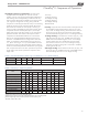
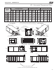
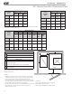
HZ - Vertical Upow Dimensional Data
Vertical
Upow
Model
Overall Cabinet
*A
Width
B
Depth
C
Height
024
in
cm
22.4
56.8
25.6
65.1
48.5
123.2
036
in
cm
25.4
64.5
30.6
77.8
50.5
128.3
048
in
cm
25.4
64.5
30.6
77.8
54.5
138.4
060 &
070
in
cm
25.4
64.5
30.6
77.8
58.5
148.6
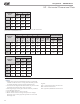
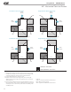
Vertical
Upow
Model
Water Connections
1 2 3 4 5
Loop
In
D
Loop
Out
E
HWG
In
F
HWG
Out
G
Cond.
H
Water
Loop
FPT
HWG
FPT
024
in
cm
3.9
9.9
8.4
21.3
13.9
35.2
16.9
42.9
6.3
16.0
3/4” 1/2”
036
in
cm
3.9
9.9
8.4
21.3
15.6
39.7
18.9
47.9
6.3
16.0
3/4” 1/2”
048
in
cm
3.9
9.9
8.4
21.3
15.6
39.7
18.9
47.9
6.3
16.0
1” 1/2”
060 &
070
in
cm
3.9
9.9
8.4
21.3
15.6
39.7
18.9
47.9
6.3
16.0
1” 1/2”
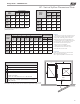
Vertical
Upow
Model
Electrical Knockouts
J
1/2”
K
1/2”
L
3/4”
Low
Voltage
External
Pump
Power
Supply
024
in
cm
3.6
9.2
6.1
15.6
8.6
21.9
036
in
cm
3.6
9.2
6.1
15.6
8.6
21.9
048
in
cm
3.6
9.2
6.1
15.6
8.6
21.9
060 &
070
in
cm
3.6
9.2
6.1
15.6
8.6
21.9
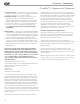
Notes:
1. While clear access to all removable panels
is not required, installer should take care to
comply with all building codes and allow
adequate clearance for future eld service.
2. Front & Side access is preferred for service
access. However, all components may be
serviced from the front access panel
if side access is not available.
3. Discharge ange is eld installed.
4. Condensate is 3/4” FPT PVC and is
switchable from front to side.
Legend:
CCP = Control/Compressor Access Panel
BSP = Blower Service Panel
ASP = (optional) Additional Service Panel
*Does not include air lter supports. Add 2” (5.1cm) when
a 1” (25.4mm) lter is used, add 3” (7.6cm) when a 2”
(50.8mm) lter is used.
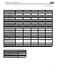
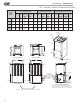
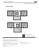
Recommended Minimum Installation Clearances for Vertical Units*
1”
Back of unit
Side opposite return air
6” Front if hard piped
Return Air Side
1”
Ducted return
- ‡ *Add for duct width
- † Add 2” for 1” lter frame/rail or 3” for 2” lter frame/rail
Free (open) return - calculate required dimension for a maximum
velocity of 600 fpm
*Field installed accessories (hoses, air cleaners, etc.) and factory WSE option will require ad-
ditional space.
Top supply air is shown, the same clearances apply to bottom supply air units.
Air Coil Side
Front
‡
†
1”
1”
1”
6”
*
Water Connections -
Units with ClimaDry
®
1 2
Loop
In D
Loop
Out E
2.1
5.2
10.0
25.4
6.0
15.1
13.1
33.4
6.0
15.1
13.1
33.4
6.0
15.1
13.1
33.4